BGP PIC functionality varies based on
the location and type of network failure.
BGP PIC core node failure
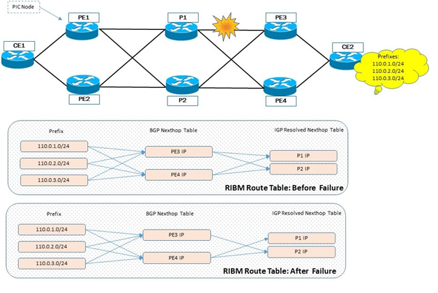
The following figure illustrates a BGP PIC core node failure and the behavior of the route tables.
BGP PIC core node failure
The behavior is as follows:
At PE1, there are two paths to each CE2 prefix,
through PE3 and PE4.
BGP next-hop PE3 is reachable through P1 and P2. The same applies to next-hop PE4.
When P1 fails, IGP invalidates the path to PE3
through P1. PE3 is now reachable only through P2.
The RIBM and FIB perform a reverse lookup to
determine which BGP next-hop is affected. Because the number of BGP next-hops is
usually less than the number of prefixes, the lookup time is reduced.
After the affected BGP next-hops are identified,
the RIBM and FIB issue a next-hop update to the hardware SDK to use the updated
list of IGP-resolved next-hops.
In the BGP PIC core node failure example, a next-hop update is
issued for BGP next-hops PE3 and PE4.
BGP PIC core link failure
The following figure illustrates a BGP PIC core link failure and the behavior of the route tables.
BGP PIC core node failure
The behavior is as follows:
At PE1, there are two paths to each CE2 prefix,
through PE3 and PE4.
BGP next-hop PE3 is reachable through P1 and P2. The same applies to next-hop PE4.
Following a P1-to-PE3 link failure, IGP invalidates
the path to PE3 through P1. PE3 is now reachable only through P2.
The RIBM and FIB perform a reverse lookup to
determine which BGP next-hop is affected. Because the number of BGP next-hops is
usually less than the number of prefixes, the lookup time is reduced.
After the affected BGP next-hops are identified,
the RIBM and FIB issue a next-hop update to the hardware SDK to use the updated
list of IGP-resolved next-hops.
PE3 is now reachable only through P2.
Consequently, the RIBM and FIB at PE1 send a next-hop update for PE3 to the
hardware SDK with the updated IGP-resolved next-hop (P2).
BGP next-hop PE4 continues to be reachable through
P1 and P2.
BGP PIC edge node failure
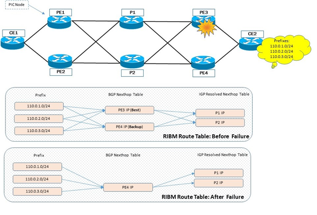
The following figure illustrates a BGP PIC edge node failure and the behavior of the route tables.
BGP PIC edge node failure
The behavior is as follows:
BGP does not form ECMP and instead provides the
backup next-hop (PE4) and the primary next-hop (PE3). Only primary next-hop is
programmed in the hardware SDK.
When PE3 fails, the RIBM and FIB at PE1 are
notified by BGP that PE3 is not reachable.
The RIBM and FIB issue a next-hop update to the
switch from PE3 to PE4 to the hardware SDK.
Traffic now flows through PE4.
BGP with eBGP primary-to-backup failure
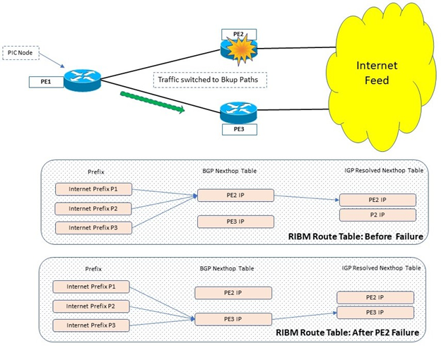
The following figure illustrates a BGP with eBGP primary-to-backup failure and the behavior of the route tables.
BGP with eBGP primary-to-backup failure
The behavior is as follows:
BGP does not form ECMP and instead provides backup
next-hop PE3 and primary next-hop PE2. Only the primary next-hop is programmed
in the hardware SDK.
When PE2 fails, the RIBM and FIB at PE1 are
notified by BGP and conclude that PE3 is not reachable.
The RIBM and FIB issue a next-hop update to the
switch from PE2 to PE3 to the hardware SDK.
Traffic now flows through PE3.
BGP with eBGP backup-to-primary failure
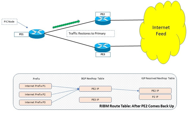
The following figure illustrates a BGP with eBGP backup-to-primary failure and the behavior of the route tables.
BGP with eBGP backup-to-primary failure
The behavior is as follows:
If PE2 comes back alive and gives the same set of routes to add to the RIBM, the
primary path is treated as restored and traffic is switched back to the primary.