Multigroup clusters allow redundancy for host devices and are supported by both VRRP and VRRP-E version 2 and version 3.
The figure below depicts a commonly employed virtual router topology. This topology introduces redundancy by configuring two virtual router groups — the first group has Router 1 as the master and Router 2 as the backup, and the second group has Router 2 as the master and Router 1 as the backup. This type of configuration is sometimes called Multigroup VRRP.
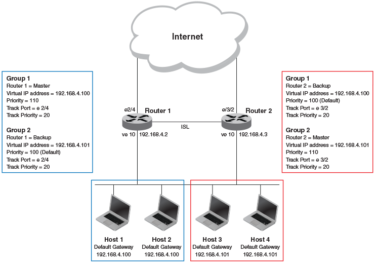
In this example, Router 1 and Router 2 use VRRP-E to load share as well as provide redundancy to the hosts. The load sharing is accomplished by creating two VRRP-E groups, each with its own virtual IP addresses. Half of the clients point to Group 1's virtual IP address as their default gateway, and the other half point to Group 2's virtual IP address as their default gateway. This enables some of the outbound Internet traffic to go through Router 1 and the rest to go through Router 2.
Router 1 is the master for Group 1 (master priority = 110) and Router 2 is the backup for Group 1 (backup priority = 100). Router 1 and Router 2 both track the uplinks to the Internet. If an uplink failure occurs on Router 1, its backup priority is decremented by 20 (track-port priority = 20) to 90, so that all traffic destined to the Internet is sent through Router 2 instead.
Similarly, Router 2 is the master for Group 2 (master priority = 110) and Router 1 is the backup for Group 2 (backup priority = 100). Router 1 and Router 2 are both tracking the uplinks to the Internet. If an uplink failure occurs on Router 2, its backup priority is decremented by 20 (track-port priority = 20) to 90, so that all traffic destined to the Internet is sent through Router 1 instead.