ML-2452-HPA5-036 Antenna Ceiling Install
About this task

Tip
The best practice is to mount the antenna on a ceiling or roof-level near the center of the coverage area.The following hardware is required for installing the antenna on
a ceiling:
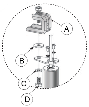
- Ceiling mount adapter plate
- Two, #6 internal tooth lock washers
- Two, #6–32 × ¼ in. SS screws
- ¼ in. internal tooth lock washer
- Ceiling hanger (grid) bracket
- 5/16 – 18 SS hex nut
Procedure
-
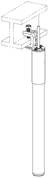
Attach the ceiling hanger
bracket to the ceiling mount adapter plate using the ¼ in. –20 hex nut and
the ¼ in. internal tooth lock washer.
The tooth lock washer must be loosely attached to the ¼ in. hex nut.
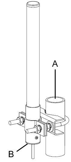
 ML-2452-HPA5-036 antenna with the ceiling hanger bracket installed
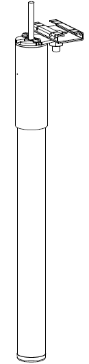
-
Secure the LMR cable along the ceiling runner using a tape or cable
ties.

Note
You need to provide the tape or cable ties. -
Attach the antenna connector to the access point connector.
MP-2452-HPA5-036 antenna ceiling installation procedure
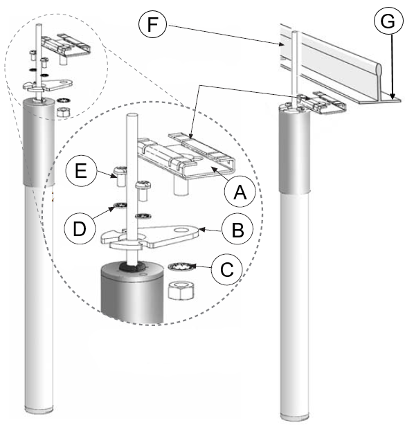
Callout Description A Ceiling hanger bracket B Ceiling mount adapter plate C ¼ in. internal tooth lock washer and 5/16 – 8 SS hex nut D #6 internal tooth lock washer E #6–32 × ¼" SS screw F Ceiling support runner G Ceiling support runner area for attaching the ceiling hanger bracket