Connecting the RPS Cable and AC Power Cord to an RPS-500p

Important

Important

When performing this task, observe all of the precautions listen in Safety Considerations for Installing Power Supplies.

Connect the RPS-500p power supply to the PoE-compliant switch using the supplied RPS cable, as follows.

Caution

Caution

Observe all ESD precautions when handling sensitive electronic equipment.
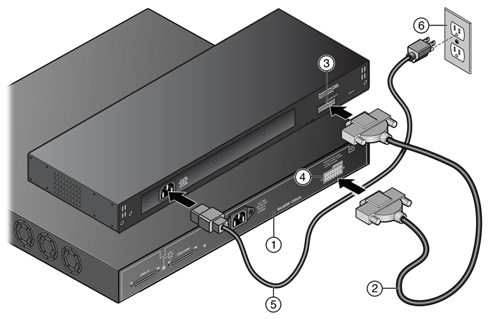
  1. Connect one end of the RPS cable to the Redundant Power Supply connector at the rear of the power supply.
  2. Connect the other end of the RPS cable to the Redundant Power Supply connector on the switch.
    See RPS Cable and AC Power Cord Connections for the RPS-500p.
    Click to expand in new window
    RPS Cable and AC Power Cord Connections for the RPS-500p
    1 = PoE-compliant switch 4 = Redundant Power Supply connector on switch
    2 = RPS cable 5 = AC power cord
    3 = Redundant Power Supply connector on power supply 6 = AC power outlet with ground connection
    Note

    Note

    AC power cords and outlets vary depending on country.
  3. Connect the AC power cord to the AC input power connector on the power supply.
  4. Plug the AC power cord into the main AC power outlet.

The AC OK and DC OK LEDs on the front of the power supply turn green to indicate that the connection was successful and the power supply is operating properly.

If the LEDs do not light properly, follow these steps to troubleshoot:

  • Check the AC power cord connection at the AC power source and make sure the power source is within specification.
  • Check the AC power connection to the power supply.
  • Swap the AC power cord with one that is known to work properly.