The RPS-150XT power supply is connected to the switch using the supplied RPS cable, as follows.

Caution
Observe all ESD precautions when handling sensitive electronic equipment.
Note
The switch should not be powered on during installation or removal of the power supply. This is not a hot-swap procedure. Follow the steps in the order specified.
Warning
For some X440-G2 models, when the RPS is not powered on and is connected to a powered switch, there is potential for a sudden load change that causes the switch to reset. It is best practice to unplug the switch before connecting the RPS.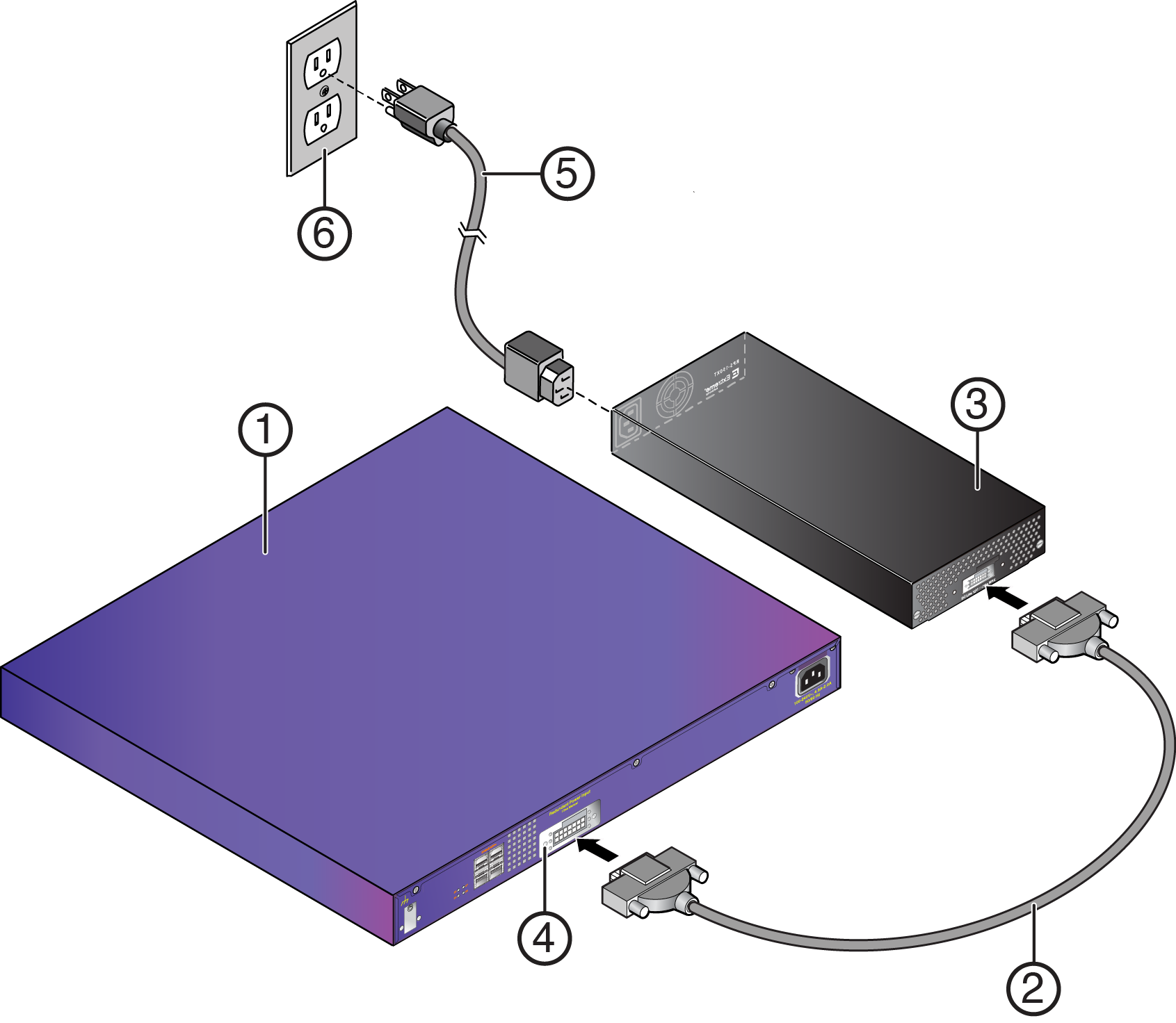
| 1 = Switch | 4 = Redundant Power Supply connector |
| 2 = RPS cable | 5 = AC power cord |
| 3 = RPS-150XT | 6 = AC power outlet with ground connection |
Note
AC power cords and outlets vary depending on country.The AC OK and DC OK LEDs on the front of the power supply turn green to indicate that the connection was successful and the power supply is operating properly.
If the LEDs do not light properly, follow these steps to troubleshoot: