You can add a new GRE tunnel configuration or edit an existing configuration.
To remove an existing GRE tunnel, select it from amongst those displayed and select the Delete button.
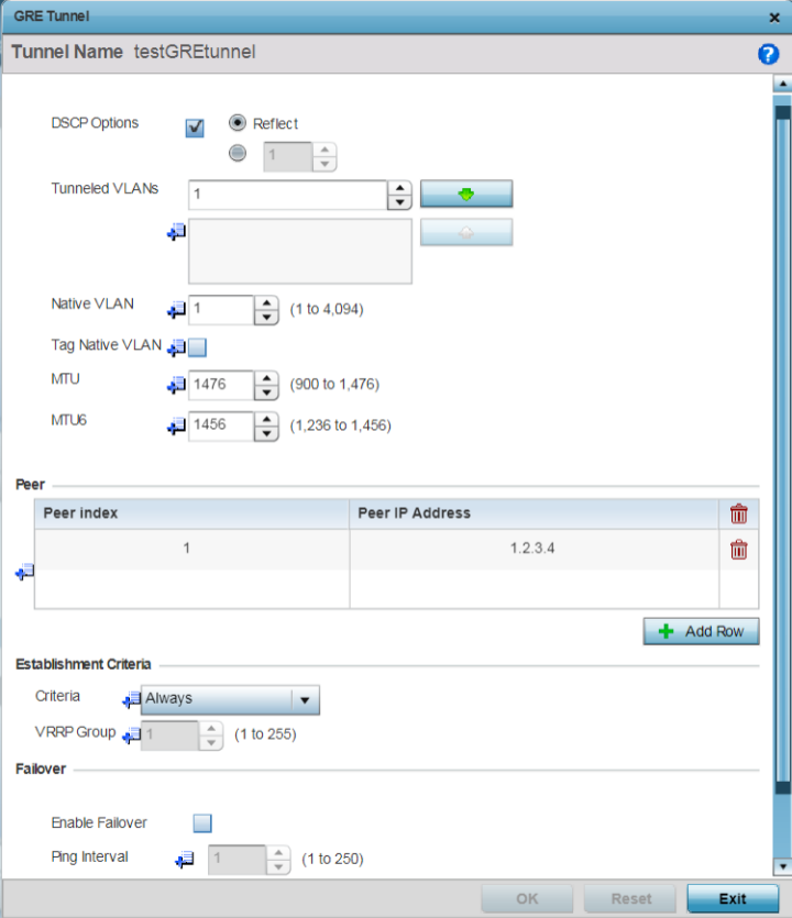
The GRE tunnel configuration screen displays.

Note
A blue override icon (to the left of a parameter) defines the parameter as having an override applied. To remove an override, go to the Basic Configuration section of the device and click the Clear Overrides button. This removes all overrides from the device.
|
DSCP Options |
Use the spinner control to set the tunnel DSCP / 802.1q priority value from encapsulated packets to the outer packet IPv4 header. |
|
Tunneled VLANs |
Define the VLAN connected clients use to route GRE tunneled traffic within their respective WLANs. |
|
Native VLAN |
Set a numerical VLAN ID (1 - 4094) for the native VLAN. The native VLAN allows an Ethernet device to associate untagged frames to a VLAN when no 802.1Q frame is included in the frame. Additionally, the native VLAN is the VLAN untagged traffic is directed over when using a port in trunk mode. |
|
Tag Native VLAN |
Select this option to tag the native VLAN. The IEEE 802.1Q specification is supported for tagging frames and coordinating VLANs between devices. IEEE 802.1Q adds four bytes to each frame identifying the VLAN ID for upstream devices that the frame belongs. If the upstream Ethernet device does not support IEEE 802.1Q tagging, it does not interpret the tagged frames. When VLAN tagging is required between devices, both devices must support tagging and be configured to accept tagged VLANs. When a frame is tagged, the 12 bit frame VLAN ID is added to the 802.1Q header so upstream Ethernet devices know which VLAN ID the frame belongs to. The device reads the 12 bit VLAN ID and forwards the frame to the appropriate VLAN. When a frame is received with no 802.1Q header, the upstream device classifies the frame using the default or native VLAN assigned to the Trunk port. The native VLAN allows an Ethernet device to associate untagged frames to a VLAN when no 802.1Q frame is included in the frame. This feature is disabled by default. |
|
MTU |
Set an IPv4 tunnel‘s MTU from 128 - 1,476. The MTU is the largest physical packet size (in bytes) transmittable within the tunnel. Any messages larger than the MTU are divided into smaller packets before being sent. A larger MTU provides greater efficiency because each packet carries more user data while protocol overheads, such as headers or underlying per-packet delays, remain fixed; the resulting higher efficiency means a slight improvement in bulk protocol throughput. A larger MTU results in the processing of fewer packets for the same amount of data. For IPv4, the overhead is 24 bytes (20 bytes IPv4 header + 4 bytes GRE Header), thus the default setting for an IPv4 MTU is 1,476. |
|
MTU6 |
Set an IPv6 tunnel‘s MTU from 128 - 1,456. The MTU is the largest physical packet size (in bytes) transmit able within the tunnel. Any messages larger than the MTU are divided into smaller packets before being sent. A larger MTU provides greater efficiency because each packet carries more user data while protocol overheads, such as headers or underlying per packet delays, remain fixed; the resulting higher efficiency means a slight improvement in bulk protocol throughput. A larger MTU results in the processing of fewer packets for the same amount of data. For IPv6, the overhead is 44 bytes (40 bytes IPv6 header + 4 bytes GRE header), thus the default setting for an IPv6 MTU is 1,456. |
The Peer table lists the credentials of the GRE tunnel end points.
|
Peer Index |
Assign a numeric index to each peer to help differentiate tunnel end points. |
|
Peer IP Address |
Define the IP address of the added GRE peer to serve as a network address identifier. |
|
Criteria |
Specify the establishment criteria for creating a GRE
tunnel. In a multicontroller within a RF domain, it‘s
always the master node with which the tunnel is
established. Depending on which of the following options
is selected, the GRE is established:
|
|
VRRP Group |
Set the VRRP group ID only enabled when the Establishment Criteria is set to vrrp-master. A virtual router redundancy group enables the creation of a group of routers as a default gateway for redundancy. Clients can point to the IP address of the VRRP virtual router as their default gateway and utilize a different group member if a master becomes unavailable. |
|
Enable Failover |
Select this option to periodically ping the primary gateway to assess its availability for failover support. |
|
Ping Interval |
Set the duration between two successive pings to the gateway. Define this value in seconds from 0 - 86,400. |
|
Number of Retries |
Set the number of retry ping opportunities before the session is terminated. |
Select Reset to revert to the last saved configuration.