Overriding a Critical Resource Configuration

About this task

Critical resources are device IP addresses or interface destinations on the network interoperated as critical to the health of the network. The critical resource feature allows for the continuous monitoring of these addresses. A critical resource, if not available, can result in the network suffering performance degradation. A critical resource can be a gateway, a AAA server, a WAN interface, or any hardware or service on which the stability of the network depends. Critical resources are pinged regularly by the access point. If there is a connectivity issue, an event is generated stating a critical resource is unavailable. By default, no critical resource policy is enabled, and one needs to be created and implemented.

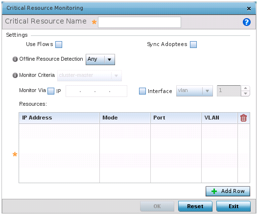
Critical resources can be monitored directly through the interfaces on which they are discovered. For example, a critical resource on the same subnet as the access point can be monitored by its IP address. However, a critical resource located on a VLAN must continue to monitored on that VLAN.

Critical resources can be configured for access points and wireless controllers using their respective profiles.

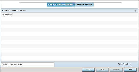
To define critical resources:

Procedure

  1. Select Configuration → Devices from the web UI.
    The Device Configuration screen displays a list of managed devices or peer controllers, service platforms, or access points.
  2. Select a target device in the lower left-hand side of the UI.
    You can also select a target device by double-clicking it in the list in the Device Configuration screen.
  3. Expand Profile Overrides and select Critical Resources.
    In the List of Critical Resources tab displays by default.
    Click to expand in new window
    Device Overrides - Critical Resources Screen - List of Critical Resources Tab
    GUID-079C38E1-BE1A-44D8-AB48-FFE6A0F2DC9F-low.png

    The screen lists the destination IP addresses or interfaces (VLAN, WWAN, or PPPoE) used for critical resource connection. IP addresses can be monitored directly by the controller, service platform, or access point. However, a VLAN, WWAN, or PPPoE must be monitored behind an interface.

  4. In the Critical Resource Name table, review the name of resources configured on this device.
  5. Click Add to add a new critical resource and connection method.

    Click Edit to modify or override the configuration for an existing critical resource.

    If you are adding a new critical resource, assign it a name up to 32 characters.

    Click to expand in new window
    Critical Resources Screen - Adding a Critical Resource
    GUID-E627E019-B3CA-478A-9DCD-727E1BA0A1B5-low.png
  6. Select Use Flows so that the critical resource will monitor using firewall flows for DHCP or DNS instead of ICMP or ARP packets.
    This reduces the amount of traffic on the network. This setting is disabled by default.
  7. Select Sync Adoptees to sync adopted devices to state changes with a resource-state change message .
    This setting is disabled by default.
  8. Use the Offline Resource Detection drop-down menu to define how critical resource event messages are generated.
    Options include Any and All. If you select Any, an event is generated when the state of any single critical resource changes. If you select All, an event is generated when the state of all monitored critical resources change.
  9. Use the Monitor Criteria drop-down menu to select either rf-domain-manager, cluster-master or All as the resource for monitoring critical resources by one device and updating the rest of the devices in a group.
    If you select rf-domain-manager, the current rf-domain manager performs resource monitoring, and the rest of the devices do not. The RF-domain-manager updates any state changes to the rest of the devices in the RF Domain.

    With the cluster-master option, the cluster master performs resource monitoring and updates the cluster members with state changes.

    With a controller-managed RF Domain, set Monitoring Criteria to All because the controller might not know the VLAN bridged locally by the devices in the RF Domain monitoring DHCP.

  10. In the Monitor Via field at the top of the screen, select the IP option to monitor a critical resource directly (within the same subnet) using the provided IP address as a network identifier.
  11. In the Monitor Via field at the top of the screen, select the Interface check box to monitor a critical resource using the critical resource‘s VLAN, WWAN1 or PPPoE1 interface.
    If you select VLAN, use the spinner control to define the destination VLAN ID used as the interface for the critical resource.
  12. Click + Add Row, in the Resources table, to define the following critical resource configurations:
    IP Address Provide the IP address of the critical resource. This is the address used by the access point to ensure the critical resource is available. Up to four addresses can be defined.
    Mode Set the ping mode used when the availability of a critical resource is validated. Select from:
    • arp-only – Use only the Address Resolution Protocol (ARP) for pinging the critical resource. ARP is used to resolve hardware addresses when only the network layer address is known.
    • arp-and-ping – Use both ARP and Internet Control Message Protocol (ICMP) for pinging the critical resource and sending control messages (for example, device not reachable or requested service not available).
    Port

    Define the interface on which to monitor critical resource. This field lists the available hardware interfaces. This option is available only when the selected mode is arp-only.

    VLAN Using the spinner control, define the VLAN on which the critical resource is available.
  13. Click OK to save the changes to the critical resource configuration and monitor interval.
    Click Reset to revert to the last saved configuration.