Overriding Basic Configuration

About this task

To edit or override the configuration of an existing port:

Before you begin

Procedure

  1. Select the port from those displayed on the screen and click Edit.

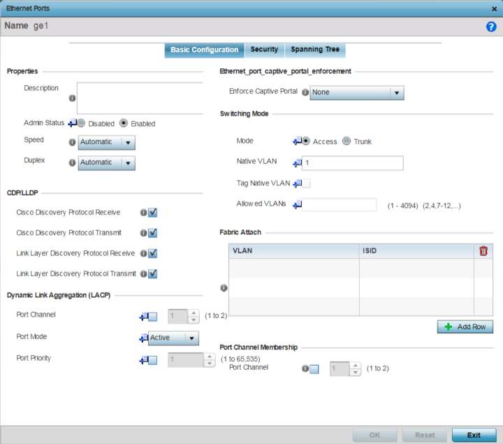
    The Ethernet Port Basic Configuration screen displays.

    Click to expand in new window
    Ethernet Ports - Basic Configuration Screen
    GUID-FB4E4A65-561A-4E92-9068-936F5EDA1E62-low.png
  2. Set or override the following Ethernet port Properties:

    Description

    Enter a brief description for the port (64 characters maximum). The description should reflect the port‘s intended function to differentiate it from others with similar configurations, or it simply can be the name of the physical port.

    Admin Status

    Select Enabled to define this port as active to the profile it supports. Select Disabled to disable this physical port in the profile. It can be activated at any time when needed. Admin status is enabled by default.

    Speed

    Select the speed at which the port can receive and transmit data, to establish a 10, 100, or 1000 Mbps data transfer rate for the selected half-duplex or full-duplex transmission.

    These options are not available if Automatic is selected. Select Automatic to enable the port to automatically exchange information about data transmission speed and duplex capabilities. Auto negotiation is helpful when in an environment where different devices are connected and disconnected on a regular basis. Automatic is the default setting.

    Duplex

    Select either Half, Full, or Automatic as the duplex option.

    Select Half duplex to send data over the port, then immediately receive data from the same direction in which the data was transmitted. Like a full-duplex transmission, a half-duplex transmission can carry data in both directions, just not at the same time.

    Select Full duplex to transmit data to and from the port at the same time. Using full duplex, the port can send data while receiving data as well.

    Select Automatic to enable to the controller or service platform to dynamically duplex as port performance needs dictate. Automatic is the default setting.

  3. Enable or disable the following CDP/LLDP parameters used to configure CDP (Cisco Discovery Protocol) and LLDP (Link Layer Discovery Protocol) for this profile‘s Ethernet port configuration:

    Cisco Discovery Protocol Receive

    Select this option to allow the Cisco discovery protocol for receiving data on this port. If enabled, the port sends out periodic interface updates to a multicast address to advertise its presence to neighbors.

    Cisco Discovery Protocol Transmit

    Select this option to allow the Cisco discovery protocol for transmitting data on this port. If enabled, the port sends out periodic interface updates to a multicast address to advertise its presence to neighbors.

    Link Layer Discovery Protocol Receive

    Select this option to allow the Link Layer discovery protocol to be received on this port. If enabled, the port sends out periodic interface updates to a multicast address to advertise its presence to neighbors. This option is enabled by default.

    Link Layer Discovery Protocol Transmit

    Select this option to allow the Link Layer discovery protocol to be transmitted on this port. If enabled, the port sends out periodic interface updates to a multicast address to advertise its presence to neighbors.

  4. Set or override the following Power Over Ethernet (PoE) parameters (if supported and applicable):

    Enable PoE

    Select this option to configure the selected controller or service platform port to use PoE (Power over Ethernet). To disable PoE on a port, uncheck this option. PoE is supported on RFS 4000 model controllers. When enabled, the controller or service platform supports 802.3af PoE on each of its ge ports. PoE allows users to monitor port power consumption and configure power usage limits and priorities for each ge port.

    Power Limit

    Use the spinner control to set the total watts available for PoE on the ge port. Set a value from 0 - 40 watts.

    Power Priority

    Set the power priority for the listed port to either to either Critical, High, or Low. This is the priority assigned to this port versus the power requirements of the other supports available on the controller or service platform.

  5. Select Enforce Captive Portal to automatically apply captive portal access permission rules to data transmitted over this specific Ethernet port.

    This setting is disabled by default.

    A captive portal is an access policy for providing temporary and restrictive access using a standard Web browser. Captive portals provides authenticated access by capturing and re-directing a wireless user's Web browser session to a captive portal login page where the user must enter valid credentials to access to the network. Once logged into the captive portal, additional Terms and Agreement, Welcome, Fail, and No Service pages provide the administrator with a number of options on captive portal screen flow and user appearance.

    Captive portal enforcement allows wired network users to pass traffic through the captive portal without being redirected to an authentication page. Authentication instead takes place when the RADIUS server is queried against the wired user's MAC address. If the MAC address is in the RADIUS server's user database, the user can pass traffic on the captive portal. If None is selected, captive portal policies are not enforced on the wired interface. If Authentication Failure is selected, captive portal policies are enforced only when RADIUS authentication of the client‘s MAC address is not successful. If Always is selected, captive portal policies are enforced regardless of whether the client's MAC address is in the RADIUS server's user database.

    For information on configuring a captive portal policy, see Captive Portal Policies.

  6. Set or override the following Switching Mode parameters to apply to the Ethernet port configuration:

    Mode

    Set the VLAN switching mode over the port: either Access or Trunk.

    If you select Access, the port accepts packets only from the native VLAN. Frames are forwarded untagged with no 802.1Q header. All frames received on the port are expected as untagged and mapped to the native VLAN.

    If you select Trunk, the port allows packets from a list of VLANs you add to the trunk. The port supports multiple 802.1Q tagged VLANs and one native VLAN which can be tagged or untagged.

    Access is the default mode.

    Native VLAN

    Define a VLAN ID (1 - 4094) for the native VLAN. The native VLAN allows an Ethernet device to associate untagged frames to a VLAN when no 802.1Q frame is included in the frame. Additionally, the native VLAN is the VLAN over which untagged traffic is directed when using a port in Trunk mode. The default VLAN is 1.

    Tag Native VLAN

    Select this option to tag the native VLAN. Controller and service platforms support the IEEE 802.1Q specification for tagging frames and coordinating VLANs between devices. IEEE 802.1Q adds four bytes to each frame identifying the VLAN ID for upstream devices that the frame belongs. If the upstream Ethernet device does not support IEEE 802.1Q tagging, it does not interpret the tagged frames. When VLAN tagging is required between devices, both devices must support tagging and be configured to accept tagged VLANs. When a frame is tagged, the 12 -bit frame VLAN ID is added to the 802.1Q header so upstream Ethernet devices know which VLAN ID the frame belongs to. The device reads the 12 bit VLAN ID and forwards the frame to the appropriate VLAN. When a frame is received with no 802.1Q header, the upstream device classifies the frame using the default or native VLAN assigned to the Trunk port. The native VLAN allows an Ethernet device to associate untagged frames to a VLAN when no 802.1Q frame is included in the frame. This feature is disabled by default.

    Allowed VLANs

    Selecting Trunk as the mode enables the Allowed VLANs parameter. Add VLANs that exclusively send packets over the listed port.

  7. In the Dynamic Link Aggregation (LACP) area, set the following parameters to enable link aggregation on the selected GE port:

    Port Channel

    Select to configure the selected port as a member of a LAG (link aggregation group). Link aggregation is supported only on the following platforms:

    AP 7562, AP 7602, AP-7612, AP-8432, AP-8533, NX 5500, NX 7500, NX 95XX, NX 96XX and VX 9000.

    LACP enables combining and managing multiple physical connections like Ethernet ports as a single logical channel as defined in the IEEE 802.1ax standard. LACP provides redundancy and increase in throughput for connections between two peers. It also provides automatic recovery in cases where one or more of the physical links - making up the aggregation - fail. Similarly, LACP also provides a theoretical boost in speed compared to an individual physical link.

    Note:

    If enabling LACP, disable or physically disconnect interfaces that do not use spanning tree to prevent loop formation until LACP is fully configured on both the local and remote devices.

    Port Mode

    Set the port mode as Active or Passive. If setting the port as a LAG member, specify whether the port is an active or passive member within the group.

    An active member initiates and participates in LACP negotiations. It is the active port that always transmits LACPDU irrespective of the remote device‘s port mode.

    The passive port only responds to LACPDU received from its corresponding active port.

    At least one port within a LAG, on either of the two negotiating peers, should be in the active mode. LACP negotiations are not initiated if all LAG member ports are passive. Further, the peer-to-peer LACP negotiations are always initiated by the peer with the lower system-priority value.

    Port Priority

    Select this option and set the selected Ethernet Port‘s priority value, within the LAG, from 1-65535.

    The selected port‘s actual priority within the LAG is determined by the port-priority value specified here along with the port‘s number. Higher the value, lower is the priority. Use this option to manipulate a port‘s priority. For example, in a LAG having five physical ports, four active and one standby, manually increasing the standby port‘s priority ensures that if one of the active port fails, the standby port is included in the LAG during re-negotiation.

  8. Click + Add Row and set or override the Fabric Attach parameters. This option enables WiNG devices (access points and controllers) as FA (Fabric Attach) clients.
    Note

    Note

    To enable FA Client feature, the Ethernet port‘s switching mode should be set to trunk.

    VLAN

    Set the VLAN from 1 - 4094.

    ISID

    User the spinner control to specify the ISID from 1 - 16777214. This is the ISID (Individual Service Identifier) associated with the VLAN interface specified above.

    Configuring a VLAN to ISID assignment, enables FA client operation on the selected Ethernet port.

    The FA Client requests acceptance of the VLAN to ISID mapping from the FAS within the FC (Fabric Connect) network. Once acceptance is achieved, the FC edge switch applies the ISID to the VLAN traffic from the device (AP or controller), and uses this ISID inside the Fabric.

    Note:

    A maximum of 94 pairs of I-SID to VLAN mappings can be configured per Ethernet port.

    FA-enabled switches, in the FC network, send out LLDP messages with TLV extensions of Organization-specific TLV with OUI, to discover FA clients and advertise capabilities.

    The FA-enabled client associates with the FAS (FA Server), and obtains provisioning information (management VLAN interface details, and whether the interface is tagged or not) that allows the client to be configured with parameters that allow traffic to flow through the Fabric to the WLAN controller. Use this option to configure the ISID to VLAN mapping that the FA Client uses to negotiate with the FAS.

    You can configure FA Client capability on a device‘s profile as well as device contexts.

  9. Optionally select Port Channel in the Port Channel Membership area, and define or override a setting from 1 - 8 using the spinner control.

    This sets the channel group for the port.

  10. Click OK to save the changes and overrides made to the Ethernet port's basic configuration.

    Click Reset to revert to the last saved configuration.