Overriding Spanning Tree Configuration

About this task

STP (Spanning Tree Protocol) (IEEE 802.1D standard) configures a meshed network for robustness by eliminating loops within the network and calculating and storing alternate paths to provide fault tolerance.

As the port comes up and STP calculation takes place, the port is set to Blocked state. In this state, no traffic can pass through the port. Since STP calculations take up to a minute to complete, the port is not operational thereby effecting the network behind the port. When the STP calculation is complete, the port‘s state is changed to Forwarding and traffic is allowed.

RSTP (Rapid Spanning Tree Protocol) (IEEE 802.1w standard) is an evolution over the standard STP. The primary aim is to reduce the time taken to respond to topology changes while being backward compatible with STP. PortFast enables quickly changing the state of a port from Blocked to Forwarding to enable the port to allow traffic while the STP calculation happens.

MSTP (Multiple Spanning Tree Protocol) provides an extension to RSTP to optimize the usefulness of VLANs. MSTOP allows for a separate spanning tree for each VLAN group, and blocks all but one of the possible alternate paths within each spanning tree topology.

If there is only one VLAN in the access point managed network, a single spanning tree works fine. However, if the network contains more than one VLAN, the network topology defined by single STP would work, but it is possible to make better use of the alternate paths available by using an alternate spanning tree for different VLANs or groups of VLANs.

An MSTP supported deployment uses multiple MST regions with multiple MSTIs (MST instances). Multiple regions and other STP bridges are interconnected using one single CST (common spanning tree). MSTP includes all of its spanning tree information in a single BPDU (Bridge Protocol Data Unit) format. BPDUs are used to exchange information bridge IDs and root path costs. Not only does this reduce the number of BPDUs required to communicate spanning tree information for each VLAN, but it also ensures backward compatibility with RSTP.

MSTP encodes additional region information after the standard RSTP BPDU as well as a number of MSTI messages. Each MSTI message conveys spanning tree information for each instance. Each instance can be assigned a number of configured VLANs. The frames assigned to these VLANs operate in this spanning tree instance whenever they are inside the MST region. To avoid conveying their entire VLAN to spanning tree mapping in each BPDU, the access point encodes an MD5 digest of their VLAN to an instance table in the MSTP BPDU. This digest is used by other MSTP supported devices to determine if the neighboring device is in the same MST region as itself.

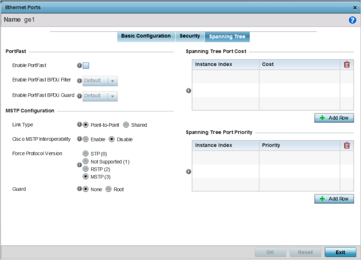
To edit or override spanning tree configuration of the selected port:

Procedure

  1. Select Spanning Tree tab.
    Click to expand in new window
    Ethernet Ports - Spanning Tree Screen
    GUID-D629DC3A-B115-4214-8107-B8BD8268A427-low.png
  2. Set the following MSTP Configuration settings:

    Enable as Edge Port

    Select this option to define this port as an edge port. Using an edge (private) port, you can isolate devices to prevent connectivity over this port.

    Link Type

    Select either Point-to-Point or Shared. When Point-to-Point is selected, the port is treated as connected to a point-to-point link. When Shared is selected, the port is shared between multiple devices.

    An example of a Point-to-Point connection is a port that is connected to a controller or service platform.

    An example of a Shared connection is a port that is connected to a hub.

    Cisco MSTP Interoperability

    Enable or Disable interoperability with Cisco‘s version of MSTP over the port. Cisco's version of MSTP is incompatible with standard MSTP.

    Force Protocol Version

    Select STP to use the standard Spanning Tree Protocol. Select RSTP to use Rapid Spanning Tree Protocol. Select MSTP to use Multiple Spanning Tree Protocol.

    Select Not Supported to disable spanning tree protocol for this interface.

    MSTP is the default setting.

    Guard

    Select Root radio to ensure that the port is a designated port. Typically, each guard root port is a designated port, unless two or more ports (within the root bridge) are connected together. If the bridge receives superior BPDUs on a guard root-enabled port, the guard root moves the port to a root-inconsistent STP state. This state is equivalent to a listening state. No data is forwarded across the port. Thus, the guard root enforces the root bridge position. Select None to disable this feature.

    Enable PortFast

    Select this option to enable drop-down menus for both the Enable PortFast BPDU Filter and Enable PortFast BPDU Guard options for the port.

    Enable PortFast BPDU Filter

    Select this option to invoke a BPDU filter for this PortFast enabled port. Enabling the BPDU filter feature ensures this PortFast enabled port does not transmit or receive BPDUs.

    Enable PortFast BPDU Guard

    Select this option to invoke a BPDU guard for this PortFast enabled port. Enabling the BPDU guard feature means that this PortFast enabled port will shut down when it receives BPDU messages.

  3. Refer to the Spanning Tree Port Cost table.

    Define or override an Instance Index using the spinner control, and set its corresponding cost in the Cost column.

    The default path cost depends on the user-defined speed of the port. The cost helps determine the role of the port in the MSTP network. The designated cost is the cost for a packet to travel from this port to the root in the MSTP configuration. The slower the media, the higher the cost.

    Table 1. Spanning Tree Port Cost

    Speed

    Default Path Cost

    <=100,000 bits/sec

    200000000

    <=1,000,000 bits/sec

    20000000

    <=10,000,000 bits/sec

    2000000

    <=100,000,000 bits/sec

    200000

    <=1,000,000,000 bits/sec

    20000

    <=10,000,000,000 bits/sec

    2000

    <=100,000,000,000 bits/sec

    200

    <=1,000,000,000,000 bits/sec

    20

    >1,000,000,000,000 bits/sec

    2

    Select + Add Row as needed to include additional indexes.

  4. Refer to the Spanning Tree Port Priority table.

    Define or override an Instance Index using the spinner control, and set its corresponding priority in the Priority column.

    The lower the priority, the greater likelihood of the port becoming a designated port. Applying a higher override value impacts the port‘s likelihood of becoming a designated port..

    Select + Add Row as needed to include additional indexes.

  5. Click OK to save the changes and overrides made to the Ethernet port's Spanning Tree configuration.

    Click Reset to revert to the last saved configuration.