Configure Access Point Radio Settings

Access points can have their radio configurations modified by their managing controller, service platform or peer access point. Take care not to modify an access point's configuration using its resident Web UI, CLI or SNMP interfaces when managed by a profile, or risk the access point having a configuration independent from the profile until the profile can be uploaded to the access point again from its managing device.

The WiNG 7.x.x OS supports the new, ExtremeMobility, 802.11ax AP3xx, AP4xx and AP5xx model access points. Refer to the following for radio and antenna details:

AP310i and AP310e radio and antenna specifications:
  • Number of Radios: 2
    • Radio 1: Dual-band, supporting 2.4GHz and 5 GHz, provides BLE support
    • Radio 2: Band locked at 5 GHz
  • AP310i - Number of Antennas:
    • Four WiFi internal antennas
    • One BLE internal antenna
  • AP310e - Number of Antennas:
    • Four WiFi external antennas
    • One BLE external antenna
AP410i and AP410e radio and antenna specifications:
  • Number of Radios: 3
    • Radio 1: Band locked at 2.4GHz; 2x2.
    • Radio 2: Band locked at 5 GHz; 4x4
    • Radio 3: 2.4 GHz and 5 GHz sensor; 2x2
  • AP410i - Number of Antennas
    • Six WiFi internal antennas
    • One BLE internal antenna
  • AP410e - Number of Antennas
    • Six WiFi external antennas
    • One BLE external antenna
AP460i and AP460e radio and antenna specifications:
  • Number of Radios: 3
    • Radio 1: Band locked at 2.4GHz; 2x2.
    • Radio 2: Band locked at 5 GHz; 4x4
    • Radio 3: 2.4 GHz and 5 GHz sensor; 2x2
  • AP460i - Number of Antennas
    • Eight WiFi internal antennas
    • One BLE internal antenna
  • AP460e - Number of Antennas
    • Eight WiFi external antennas
    • One BLE external antenna
AP505i radio and antenna specifications:
  • Number of Radios: 2
    • Radio 1: Band locked at 2.4GHz. provides Bluetooth Low Energy (BLE) support
    • Radio 2: Band locked at 5 GHz
  • Number of Antennas:
    • Eight WiFi internal antennas
    • One BLE internal antenna
AP510i radio and antenna specifications:
  • Number of Radios: 2
    • Radio 1: Dual-band, supporting 2.4GHz and 5 GHz, provides BLE support
    • Radio 2: Band locked at 5 GHz
  • Number of Antennas:
    • Eight WiFi internal antennas
    • One BLE internal antenna
AP510e radio and antenna specifications:
  • Number of Radios: 2
    • Radio 1: Dual-band, supporting 2.4GHz and 5 GHz, provides BLE support
    • Radio 2: Band locked at 5 GHz
  • Number of Antennas:
    • Eight WiFi external antennas, with the antenna ports grouped into:
      • group 1 - comprising of antennas 1, 2, 3, and 4
      • group 2 - comprising of antennas 5, 6, 7 and 8
    • One BLE internal antenna
AP560i radio and antenna specifications:
  • Number of Radios: 2
    • Radio 1: Dual-band, supporting 2.4GHz and 5 GHz, provides BLE support
    • Radio 2: Band locked at 5 GHz
  • Number of Antennas:
    • Eight WiFi internal antennas
    • One BLE internal antenna
AP560h radio and antenna specifications:
  • Number of Radios: 2
    • Radio 1: Dual-band, supporting 2.4GHz and 5 GHz, provides BLE support
    • Radio 2: Band locked at 5 GHz
  • Number of Antennas:
    • Eight WiFi internal antennas, supporting the following internal antenna modes:
      • 30 degree
      • 70 degree
    • One BLE internal antenna

To define an access point radio configuration from an associated peer access point controller AP, controller or NX service platform:

  1. Select Configuration → Devices → System Profile from the web UI.

    A list of device profiles is displayed in the right-hand UI. This list contains default and user-defined profiles.

  2. Select a profile from those listed on the screen.

    The profile's configuration menu is displayed.

  3. Expand the Interface menu and select Radios.
    Click to expand in new window
  4. Review the following to determine whether a radio configuration requires modification to better support the managed network:
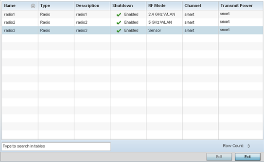
    Name Displays whether the reporting radio is the access point's radio1, radio2 or radio3.
    Type Displays the type of radio housed by each listed access point.
    Description Displays a brief description of the radio provided by the administrator when the radio's configuration was added or modified.
    Admin Status A green checkmark defines the listed radio as active and enabled with its supported profile. A red "X" defines the radio as currently disabled.
    RF Mode Displays whether each listed radio is operating in the 802.11a/n or 802.11b/g/n radio band. If the radio is a dedicated sensor, it will be listed as a sensor to define the radio as not providing typical WLAN support. If the radio is a client-bridge, it provides a typical bridging function and does not provide WLAN support. The radio band is set from within the Radio Settings tab.
    Channel Lists the channel setting for the radio. Smart is the default setting. If set to smart, the access point scans non-overlapping channels listening for beacons from other access points. After the channels are scanned, it selects the channel with the fewest access points. In the case of multiple access points on the same channel, it selects the channel with the lowest average power level.
    Transmit Power Lists the transmit power for each radio displayed as a value in milliwatts.
  5. If required, select a radio configuration and select the Edit button to modify its configuration.