To define a GRE configuration:
Select Configuration > Profiles > Network.
Expand the Network menu to display its submenu options.
Select GRE.
The screen displays existing GRE configurations.
Select the Add button to create a new GRE tunnel configuration or select an existing tunnel and select Edit to modify its current configuration. To remove an existing GRE tunnel, select it from amongst those displayed and select the Delete button.
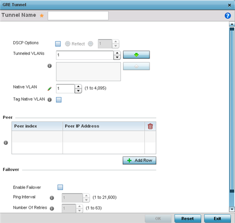
If creating a new GRE configuration, assign it a name to distinguish its configuration.
Define the following settings for the GRE configuration:
|
DSCP Options |
Use the spinner control to set the tunnel DSCP / 802.1q priority value from encapsulated packets to the outer packet IPv4 header. |
|
Tunneled VLANs |
Define the VLAN connected clients use to route GRE tunneled traffic within their respective WLANs. |
|
Native VLAN |
Set a numerical VLAN ID (1 - 4094) for the native VLAN. The native VLAN allows an Ethernet device to associate untagged frames to a VLAN when no 802.1Q frame is included in the frame. Additionally, the native VLAN is the VLAN untagged traffic is directed over when using a port in trunk mode. |
|
Tag Native VLAN |
Select this option to tag the native VLAN. The IEEE 802.1Q specification is supported for tagging frames and coordinating VLANs between devices. IEEE 802.1Q adds four bytes to each frame identifying the VLAN ID for upstream devices that the frame belongs. If the upstream Ethernet device does not support IEEE 802.1Q tagging, it does not interpret the tagged frames. When VLAN tagging is required between devices, both devices must support tagging and be configured to accept tagged VLANs. When a frame is tagged, the 12 bit frame VLAN ID is added to the 802.1Q header so upstream Ethernet devices know which VLAN ID the frame belongs to. The device reads the 12 bit VLAN ID and forwards the frame to the appropriate VLAN. When a frame is received with no 802.1Q header, the upstream device classifies the frame using the default or native VLAN assigned to the Trunk port. The native VLAN allows an Ethernet device to associate untagged frames to a VLAN when no 802.1Q frame is included in the frame. This feature is disabled by default. |
The Peer table lists the credentials of the GRE tunnel end points. Add new table rows as needed to add additional GRE tunnel peers.
Select + Add Row to populate the table with a maximum of two peer configurations.
Define the following Peer parameters:
|
Peer Index |
Assign a numeric index to each peer to help differentiate tunnel end points. |
|
Peer IP Address |
Define the IP address of the added GRE peer to serve as a network address identifier. |
Define the following Failover parameters to apply to the GRE tunnel configuration:
|
Enable Failover |
Select this option to periodically ping the primary gateway to assess its availability for failover support. |
|
Ping Interval |
Set the duration between two successive pings to the gateway. Define this value in seconds from 0 - 86,400. |
|
Number of Retries |
Set the number of retry ping opportunities before the session is terminated. |
Select the OK button located to save the changes. Select Reset to revert to the last saved configuration.
 Print
this page
Print
this page Email this topic
 Feedback
 View PDF
 Download EPUB