WiNG provides a dataplane bridge for external network connectivity for Virtual Machines (VMs). VM Interfaces define which IP address is associated with each VLAN ID the service platform is connected to and enables remote service platform administration. Each custom VM can have up to a maximum of two VM interfaces. Each VM interface can be mapped to one of sixteen VMIF ports on the dataplane bridge. This mapping determines the destination for service platform routing.
By default, VM interfaces are internally connected to the dataplane bridge via VMIF1. VMIF1 is an untagged port providing access to VLAN 1 to support the capability to connect the VM interfaces to any of the VMIF ports. This provides the flexibility to move a VM interface onto different VLANs as well as configure specific firewall and QOS rules.

Note
VM interfaces are only supported for NX4500, NX6500 and NX9000 series service platforms.To define a VM interface profile configuration:
Select Configuration > Profiles > Interface.
Expand the Interface menu to display its submenu options.
Select VM.
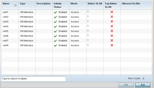
Refer to the following to review VM interface configurations and status:
|
Name |
Displays the VM interface numerical identifier assigned when it was created. The numerical name cannot be modified as part of the edit process. |
|
Type |
Displays whether the type is VM interface. |
|
Description |
Lists a short description (64 characters maximum) describing the VM interface or differentiating it from others with similar configurations. |
|
Admin Status |
A green check mark defines the listed VM interface as active and currently enabled with the profile. A red “X” defines the VM interface as currently disabled and not available for use. The interface status can be modified with the VM interface Basic Configuration screen as required. |
|
Mode |
Displays the layer 3 mode of the VM interface as either Access or Trunk (as defined within the VM Interfaces Basic Configuration screen). If Access is selected, the listed VM interface accepts packets only from the native VLAN. Frames are forwarded untagged with no 802.1Q header. All frames received on the port are expected as untagged and mapped to the native VLAN. If set to Trunk, the port allows packets from a list of VLANs added to the trunk. A VM interface configured as Trunk supports multiple 802.1Q tagged VLANs and one Native VLAN which can be tagged or untagged. |
|
Native VLAN |
Lists the numerical VLAN ID (1 - 4094) set for the native VLAN. The native VLAN allows a VM interface to associate untagged frames to a VLAN when no 802.1Q frame is included in the frame. Additionally, the native VLAN is the VLAN untagged traffic is directed over when using a VM interface in trunk mode. |
|
Tag Native VLAN |
A green check mark defines the native VLAN as tagged. A red “X” defines the native VLAN as untagged. When a frame is tagged, the 12 bit frame VLAN ID is added to the 802.1Q header so upstream VM interface ports know which VLAN ID the frame belongs to. The device reads the 12 bit VLAN ID and forwards the frame to the appropriate VLAN. When a frame is received with no 802.1Q header, the upstream VM interface classifies the frame using the default or native VLAN assigned to the Trunk port. A native VLAN allows a VM interface to associate untagged frames to a VLAN when no 802.1Q frame is included in the frame. |
|
Allowed VLANs |
Displays those VLANs allowed to send packets over the listed VM interface. Allowed VLANs are only listed when the mode has been set to Trunk. |
To edit the configuration of an existing VM interface, select it from amongst those displayed and select the Edit button.
 Print
this page
Print
this page Email this topic
 Feedback
 View PDF
 Download EPUB