A radio's profile configuration is customizable to define how transmit and receive data frames are processed. A radio's sniffer redirect settings can be refined to adjust how captured packets are directed. Additionally, channel scanning settings can refined in respect to channel scanning requirements on either the 2.4 or 5 GHz radio bands.
To a radio's advanced settings:
Select Configuration > Profiles > Interface.
Expand the Interface menu to display its submenu options.
Select Radios.
If required, select a radio configuration and select the Edit button to modify its configuration.
Select the Advanced Settings tab.
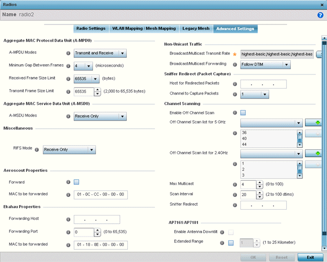
Refer to the Aggregate MAC Protocol Data Unit (A-MPDU) field to define how MAC service frames are aggregated by the access point radio.
|
A-MPDU Modes |
Use the drop-down menu to define the A-MPDU mode supported. Options include Transmit Only, Receive Only, Transmit and Receive and None. The default value is Transmit and Receive. Using the default value, long frames can be both sent and received (up to 64 KB). When enabled, define either a transmit or receive limit (or both). |
|
Minimum Gap Between Frames |
Use the drop-down menu to define the minimum gap between A-MPDU frames (in microseconds). The default value is 4 microseconds. |
|
Received Frame Size Limit |
If a support mode is enabled allowing A-MPDU frames, define an advertised maximum limit for received A-MPDU aggregated frames. Options include 8191, 16383, 32767 or 65535 bytes. The default value is 65535 bytes. |
|
Transmit Frame Size Limit |
Use the spinner control to set limit on transmitted A-MPDU aggregated frames. The available range is between 0 - 65,535 bytes). The default value is 65535 bytes. |
Use the A-MSDU Modes drop-down menu in the Aggregate MAC Service Data Unit (A-MSDU) section to set the supported A-MSDU mode.
Available modes include Receive Only and Transmit and Receive. Transmit and Receive is the default value. Using Transmit and Receive, frames up to 4 KB can be sent and received. The buffer limit is not configurable.
Set the following Aeroscout Properties:
|
Forward |
Select enable to forward Aeroscout packets to a specified MAC address. Aeroscout tags associate with an access point, then communicate with a location engine. This setting is disabled by default. |
|
MAC to be Forwarded |
Specify the MAC address to be forwarded. |
Set the following Ekahau Properties:
|
Forward Host |
Specify the Ekahau engine IP address. Using Ekahau small, battery powered Wi-Fi tags are attached to tracked assets or carried by people. Ekahau processes locations, rules, messages and environmental data and turns the information into locationing maps, alerts and reports. |
|
Forwarding Host |
Use the spinner control to set the Ekahau TZSP port used for processing information from locationing tags. |
|
MAC to be Forwarded |
Specify the MAC address to be forwarded. |
Set the following Non-Unicast Traffic values for the profile's supported access point radio and its connected wireless clients:
|
Broadcast/Multicast Transmit Rate |
Use the drop-down menu to define the data rate broadcast and multicast frames are transmitted. Seven different rates are available if the not using the same rate for each BSSID, each with a separate menu. |
|
Broadcast/Multicast Forwarding |
Define whether client broadcast and multicast packets should always follow DTIM, or only follow DTIM when using Power Save Aware mode. The default setting is Follow DTIM. |
Refer to the Sniffer Redirect (Packet Capture) field to define the radio's captured packet configuration.
|
Host for Redirected Packets |
If packets are re-directed from a connected access point radio, define an IP address resource (additional host system) to capture the re-directed packets. This address is the numerical (non DNS) address of the host used to capture re-directed packets. |
|
Channel to Capture Packets |
Use the drop-down menu to specify the specific channel used to capture re-directed packets. The default value is channel 1. |
Refer to the Channel Scanning field to define the radio‘s captured packet configuration.
|
Enable Off Channel Scan |
Enable this option to scan across all channels using this radio. Channel scans use access point resources and can be time consuming, so only enable when your sure the radio can afford the bandwidth be directed towards to the channel scan and does not negatively impact client support. |
|
Off Channel Scan list for 5GHz |
Define a list of channels for off channel scans using the 5GHz access point radio. Restricting off channel scans to specific channels frees bandwidth otherwise utilized for scanning across all the channels in the 5GHz radio band. |
|
Off Channel Scan list for 2.4GHz |
Define a list of channels for off channel scans using the 2.4GHz access point radio. Restricting off channel scans to specific channels frees bandwidth otherwise utilized for scanning across all the channels in the 2.4GHz radio band. |
|
Max Multicast |
Set the maximum number (from 0 - 100) of multicast/broadcast messages used to perform off channel scanning. The default setting is four. |
|
Scan Interval |
Set the interval (from 2 - 100 dtims) off channel scans occur. The default setting is 20dtims. |
|
Sniffer Redirect |
Specify the IP address of the host to which captured off channel scan packets are redirected. |
Set the following AP7161/AP7181 settings:
|
Enable Antenna Downtilt |
Enable this settings (on AP7181 models only) to allow the access point to physically transmit in a downward orientation (ADEPT mode). |
|
Extended Range |
Set an extended range (from 1 - 25 kilometers) to allow AP7161 and AP7181 model access points to transmit and receive with their clients at greater distances without being timed out. |
Select OK to save the changes to the advanced settings screen. Select Reset to revert to the last saved configuration.
 Print
this page
Print
this page Email this topic
 Feedback
 View PDF
 Download EPUB