To define an L2TPV3 configuration for a profile:
Select Configuration > Profiles > Network.
Expand the Network menu to display its submenu options.
Expand the Network menu and select L2TPv3.
Select the L2TPv3 Tunnel tab.
Either select Add to create a new L2TPv3 tunnel configuration, Edit to modify an existing tunnel configuration or Delete to remove a tunnel from those available to this profile.
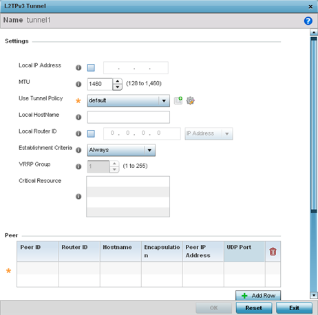
If creating a new tunnel configuration, assign it a 31 character maximum Name.
Define the following Settings required for the L2TP tunnel configuration:
|
Local IP Address |
Enter the IP address assigned as the local tunnel end point address, not the interface IP address. This IP is used as the tunnel source IP address. If this parameter is not specified, the source IP address is chosen automatically based on the tunnel peer IP address. This parameter is applicable when establishing the tunnel and responding to incoming tunnel create requests. |
|
MTU |
Set the maximum transmission unit (MTU). The MTU is the size (in bytes) of the largest protocol data unit the layer can pass between tunnel peers. Define a MTU from 128 - 1,460 bytes. The default setting is 1,460. A larger MTU means processing fewer packets for the same amount of data. |
|
Use Tunnel Policy |
Select the L2TPv3 tunnel policy. The policy consists of user defined values for protocol specific parameters which can be used with different tunnels. If none is available, a new policy can be created or an existing one can be modified. |
|
Local Hostname |
Provide the tunnel specific hostname used by this tunnel. This is the host name advertised in tunnel establishment messages. |
|
Local Router ID |
Specify the router ID sent in tunnel establishment messages with a potential peer device. |
Refer to the Peer table to review the configurations of the peers available for tunnel connection.
Select + Add Row to populate the table with a maximum of two peer configurations.
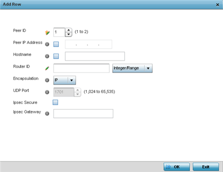
Define the following Peer parameters:
|
Peer ID |
Define the primary peer ID used to set the primary and secondary peer for tunnel failover. If the peer is not specified, tunnel establishment does not occur. However, if a peer tries to establish a tunnel with this access point, it creates the tunnel if the hostname and/or Router ID matches. |
|
Peer IP Address |
Select this option to enter the numeric IP address used as the tunnel destination peer address for tunnel establishment. |
|
Host Name |
Assign the peer a hostname used as matching criteria in the tunnel establishment process. |
|
Router ID |
Specify the router ID sent in tunnel establishment messages with this specific peer. |
|
Encapsulation |
Select either IP or UDP as the peer encapsulation protocol. The default setting is IP. UDP uses a simple transmission model without implicit handshakes. |
|
UDP Port |
If UDP encapsulation is selected, use the spinner control to define the UDP encapsulation port. |
Select OK to save the peer configuration.
Refer to the Session table to review the configurations of the peers available for tunnel connection.
Select + Add Row to populate the table with configurable session parameters for this tunnel configuration.
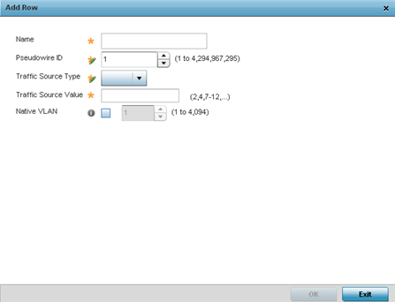
Define the following Session parameters:
|
Name |
Enter a 31 character maximum session name. There is no idle timeout for a tunnel. A tunnel is not usable without a session and a subsequent session name. The tunnel is closed when the last session tunnel session is closed. |
|
Pseudowire ID |
Define a psuedowire ID for this session. A pseudowire is an emulation of a layer 2 point-to-point connection over a packet-switching network (PSN). A pseudowire was developed out of the necessity to encapsulate and tunnel layer 2 protocols across a layer 3 network. |
|
Traffic Source Type |
Lists the type of traffic tunneled in this session. |
|
Traffic Source Value |
Define a VLAN range to include in the tunnel session. Available VLAN ranges are from 1 - 4,094. |
|
Native VLAN |
Select this option to provide a VLAN ID that will not be tagged in tunnel establishment and packet transfer. |
Select OK to save the changes within the L2TP Tunnel screen. Select Reset to revert the screen to its last saved configuration.
 Print
this page
Print
this page Email this topic
 Feedback
 View PDF
 Download EPUB