The example shown in the following figure uses four Extreme Networks devices as edge switches that perform Layer 2 switching for VLAN Sales.
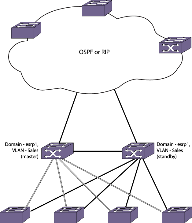
In the figure above, the ESRP master performs both Layer 2 switching and Layer 3 routing services for VLAN Sales. To prevent bridging loops in the VLAN, the ESRP slave performs no switching or routing for VLAN Sales while the ESRP master is operating.
There are four paths between each ESRP switch and the edge switches for VLAN Sales. All the paths are used to send ESRP packets, allowing for four redundant paths for communication. The edge switches, being ESRP-aware, allow traffic within the VLAN to failover quickly because these edge switches sense when a master/slave transition occurs and flush FDB entries associated with the uplinks to the ESRP-enabled switches.
ESRP election algorithm used is the default for standard mode (ports > track > priority > mac).
The inter-router backbone is running OSPF, with other routed VLANs already properly configured. Similar commands would be used to configure a switch on a network running RIP.
Ports added to the VLAN have already been removed from VLAN default.
The same IP address is specified for all VLANs participating in ESRP.

Note
If your network has switches running ExtremeWare and ExtremeXOS software participating in ESRP, we recommend that the ExtremeXOS switches operate in ESRP standard mode. To change the mode of operation, use the command:
The following commands are used to configure both ESRP switches:
create vlan sales
configure vlan sales add ports 1:1-1:4
configure vlan sales ipaddress 10.1.2.3/24
enable ipforwarding
create esrp esrp1
configure esrp esrp1 domain-id 4096
configure esrp esrp1 add master sales
enable esrp esrp1
configure ospf add vlan sales area 0.0.0.0 passive
configure ospf routerid 5.5.5.5
enable ospf
 Print
this page
Print
this page Email this topic
 Feedback
 View PDF
 Download EPUB