TRILL running on the BlackDiamond X8 core switch and the Summit X670, or X770, top-of-rack switch can solve these requirements. The following reference network diagram has been simplified. Typically the top-of-rack Summit X670 switches have four or eight up-links into multiple core switches (highlighted in magnified view at the bottom-right of the diagram). This reduces the number of hops and end-to-end latency and also offers increased resiliency.
The first three challenges are met by deploying the BlackDiamond X8 and Summit X670 with 10G, 40G, and 100G Ethernet links in the DC. Multiple 40G links can be trunked together to form 160G or 320G core links. Each Summit X670 supports 48 front-panel 10G Ethernet links. Given the typical dual Ethernet connected server configuration, each Summit X670 provides core network access for 24 servers. Each BlackDiamond X8 supports 192 40G and 768 10G Ethernet ports. Scaling a fully meshed network core is limited by the (Node)2 link requirement. This introduces topology challenges that TRILL addresses.
A large flat Layer 2 network that allows any-to-any connectivity with lots of devices and high interconnect speeds may be implemented with a single VLAN domain. To prevent loops, Layer 2 protocols must be introduced that limit network link usability. TRILL retains the benefits of Layer 2 networks and adds the capabilities of IP Routing. This includes maintaining and building a complete link state network topology. TRILL also supports ECMP next-hop routing look up and packet forwarding operation. Similar to ISIS and OSPF, TRILL uses a modified Hello Protocol to discover neighbors and exchange capabilities information.
By combining the useful attributes of Layer 3 to the simplicity of Layer 2, TRILL addresses the Data Center core requirements better than either Layer 2-only or Layer 3-only designed networks.
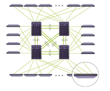
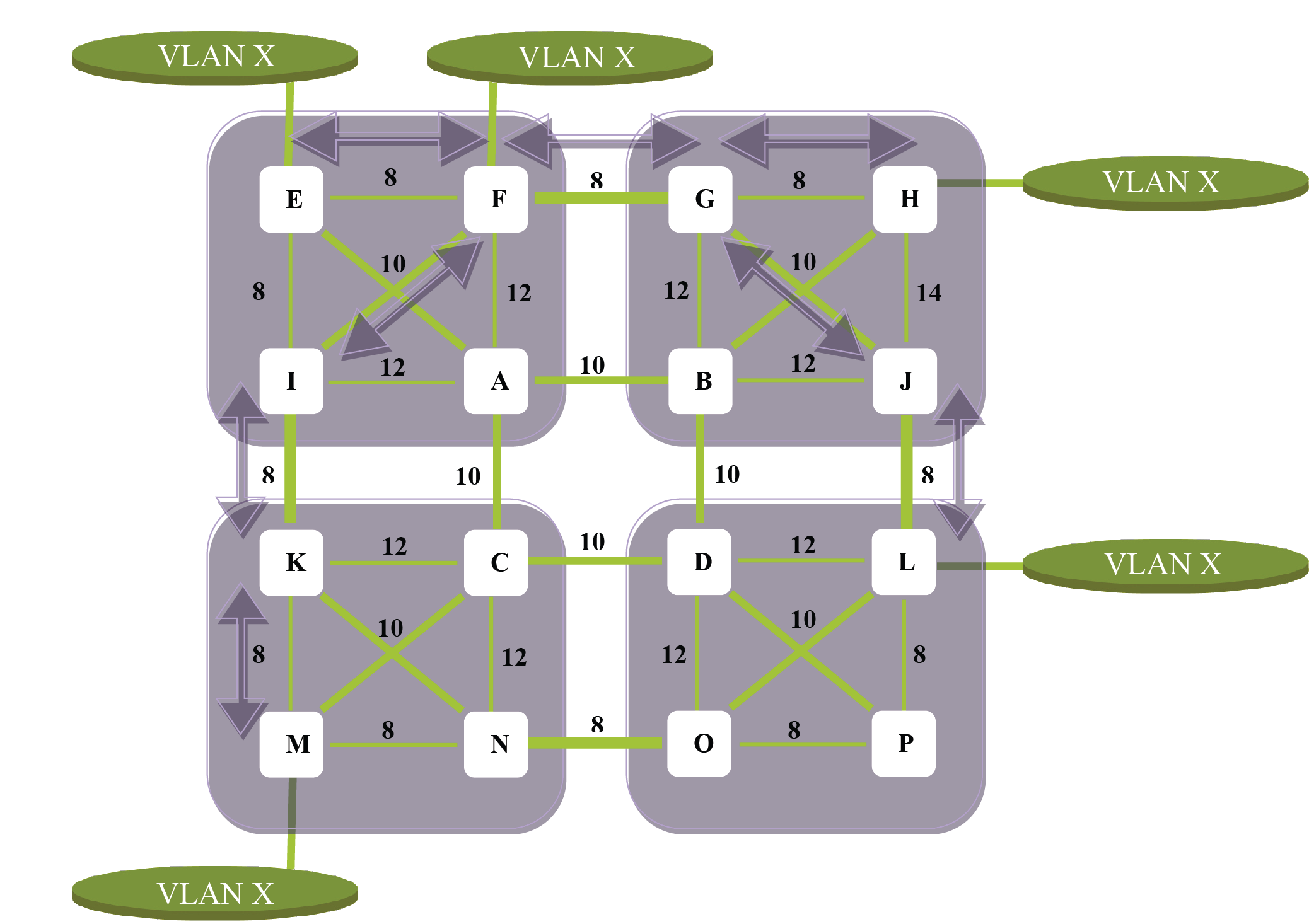
TRILL uses the link state path computation, known as the Dijkstra Algorithm, to calculate the best path route based on link cost to every node in the network. Each node makes an independent decision on where to send a packet based on the packet‘s destination egress node. Given the quad-core network layout shown above, interconnect links have been added and associated link costs are shown in the figure above.
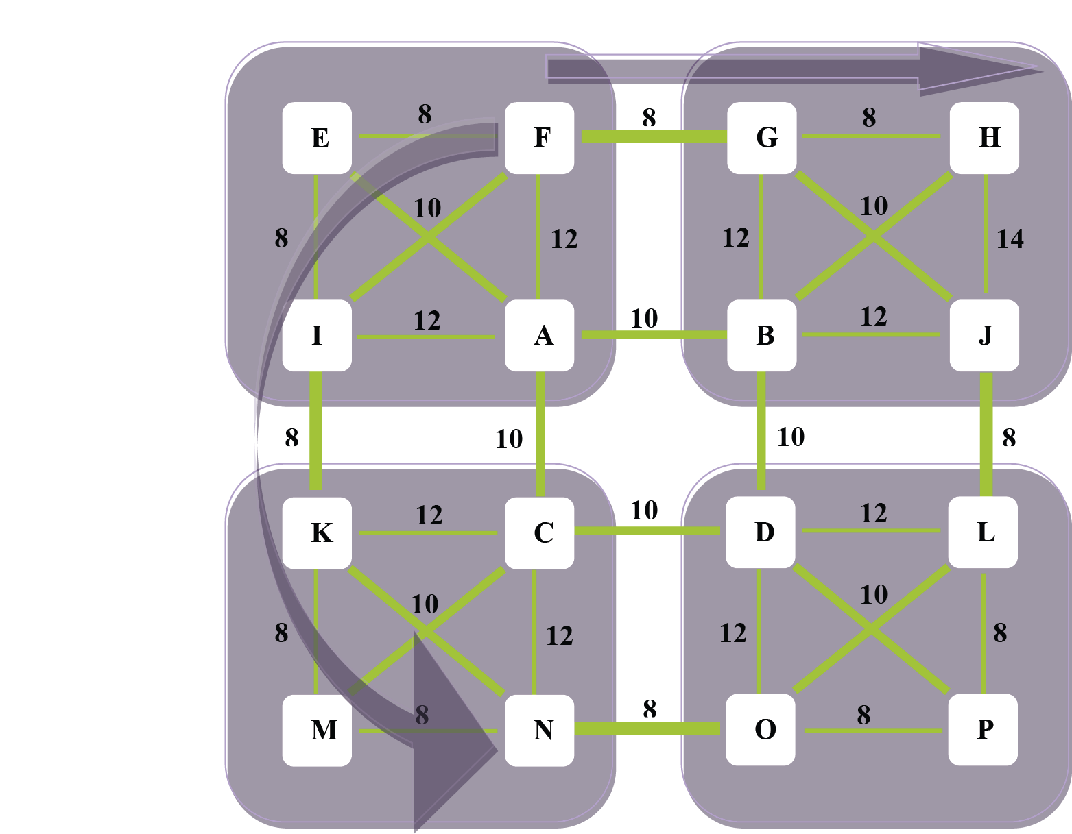
If a packet enters the network at node F and egresses the network at node H, the best path is F > G > H with a cost of 16. If the packet enters the network at node F and egresses at node N, the best path is F > I > K > N with a cost of 28. This means that multiple paths through the network are utilized.

Note
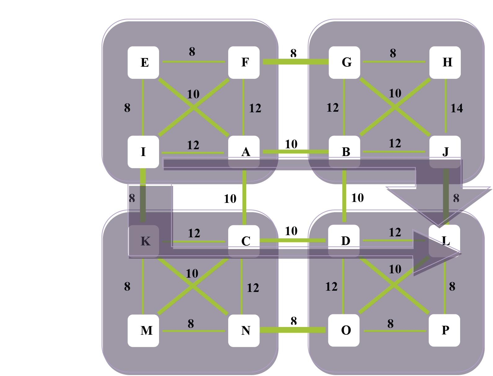
With respect to ECMP TRILL forwarding, bi-directional packet flows may not take the same path. This is an artifact of the hash algorithm operating on encapsulated packet headers that are formatted differently and the specific hash algorithm implemented.Logically, the Data Center network can be considered to have two independent sets of 4K VLANs: one set for the access devices and one set for the TRILL core network. Each TRILL node, or Route Bridge (RBridge), has a configured set of Access VLAN IDs that it provides traffic forwarding. To maintain full plug-and-play capability, the VLAN access list encompasses the entire 4K VLAN ID space. Native Ethernet tagged traffic received on a VLAN with a VLAN ID that matches an ID in the access tag space is encapsulated and forwarded across the TRILL network as shown in the following figure:
Note
Although TRILL supports this, multiple distribution trees are not supported in the initial release of TRILL.Optionally, each RBridge can restrict forwarding of packets with VLAN tags to only those tree adjacencies that have downstream matching Access VLANs. This type of packet filtering eliminates unnecessary packet forwarding with in the TRILL core. Distribution trees are bi-directional and can be rooted at any node. This is referred to as VLAN pruning. The previous figure shows a TRILL network with VLAN X attached at RBridge nodes E, F, H, L, and M.
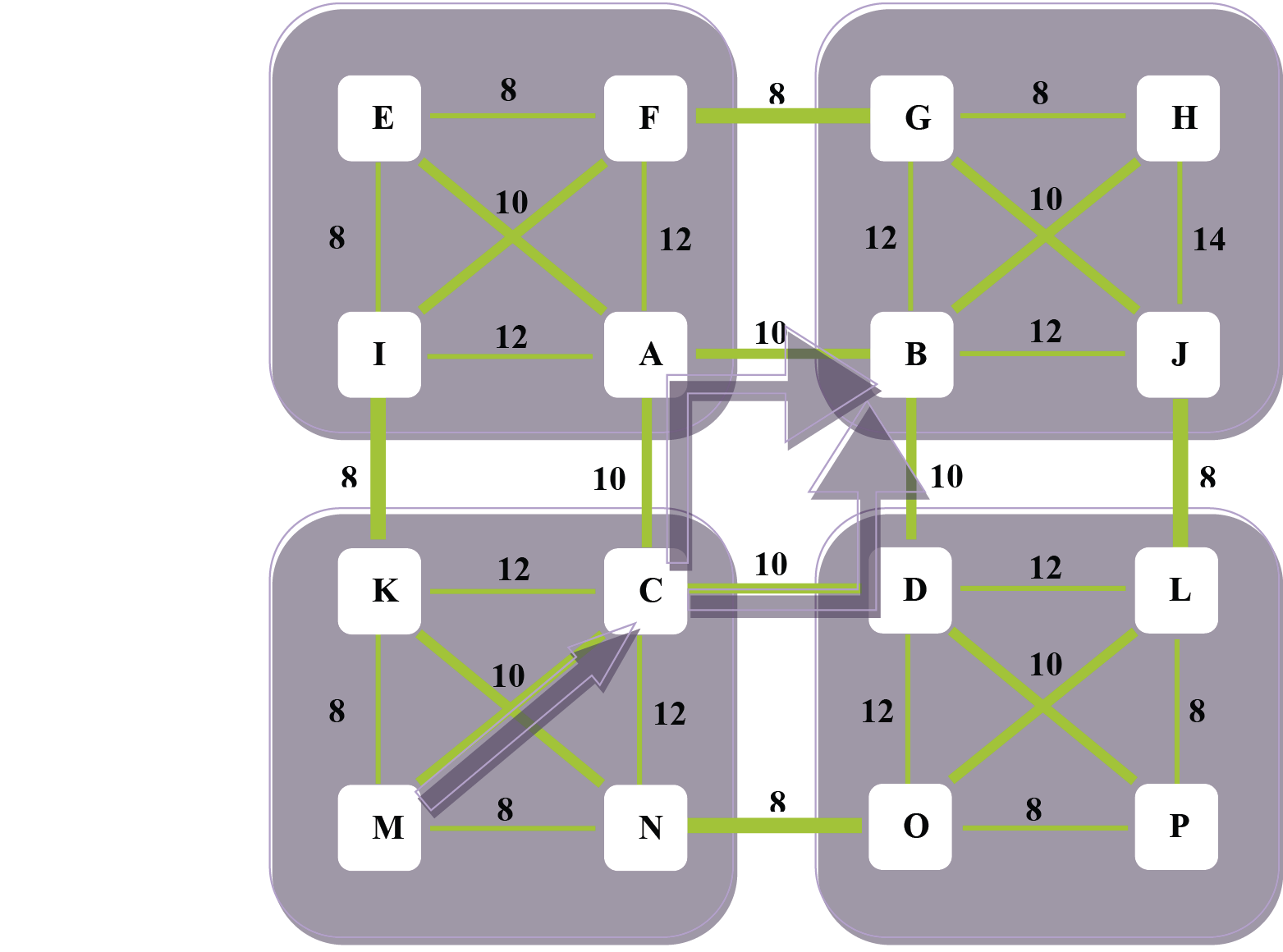
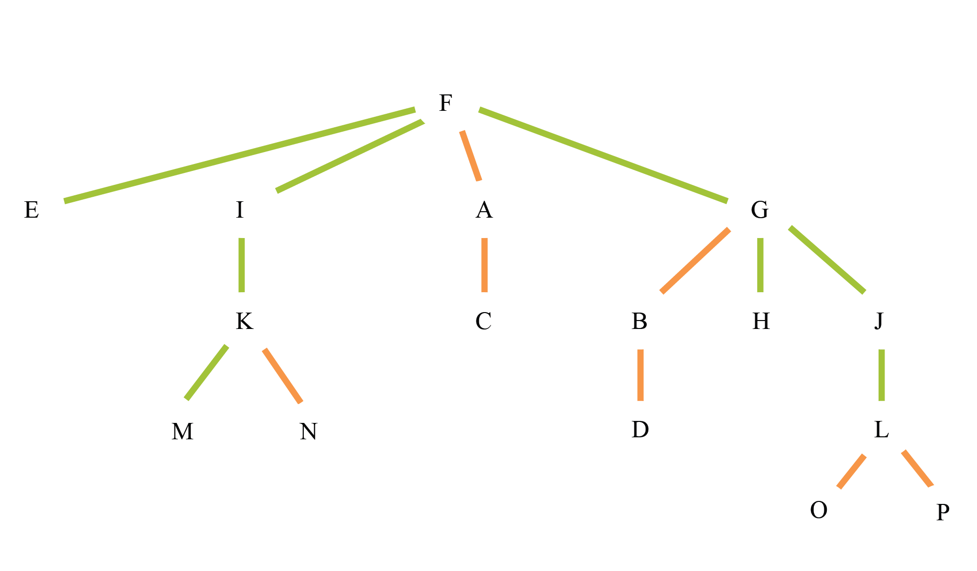
One potential general distribution tree is shown in the following figure. Distribution trees may be rooted at multiple RBridges. VLAN X access RBridges are colored green. In the example below, RBridge F is configured with the highest priority distribution tree and thus is used by all the RBridges in the TRILL network to forward flood and multicast traffic. All RBridges in the network must maintain the same topological view and be able to calculate the same distribution trees. For VLAN X, RBridges F, K, G, and L are not required to forward traffic to some or all of the distribution tree adjacencies. This effectively prunes the distribution tree and reduces packet replication and unnecessary traffic forwarding. Pruned RBridge nodes that will not receive VLAN X traffic are colored orange. If the distribution tree pruning is not employed by RBridges, the RBridge leaves must still discard any received traffic on VLAN X, provided no locally configured Access VLANs for VLAN X.
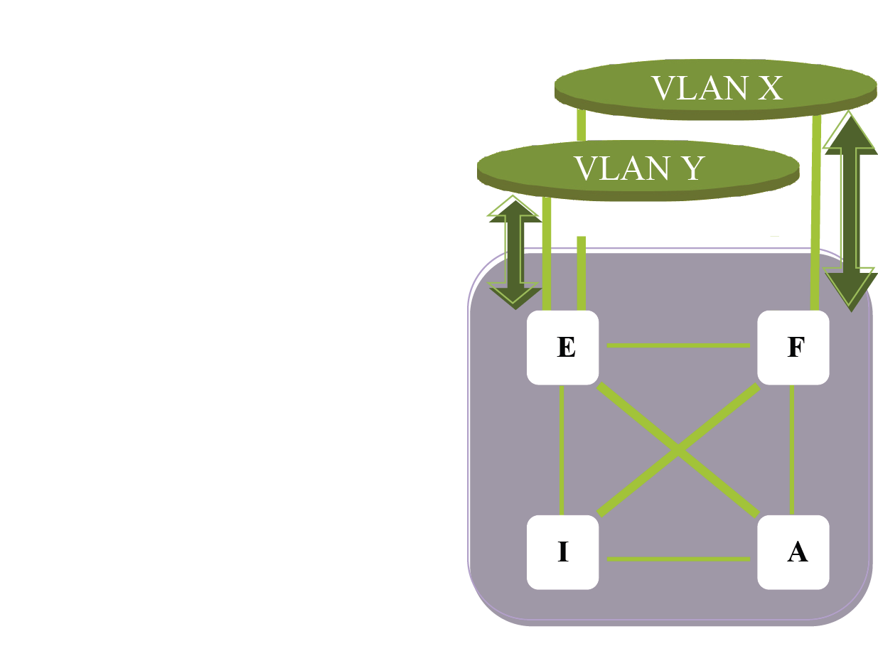
TRILL adds load sharing improvements on the access interfaces. VLANs may optionally be connected to multiple RBridges, as shown in the previous figure. The Designated RBridge determines which node provides forwarding access for each attached VLAN. RBridges providing packet forwarding are referred to as the appointed forwarders. The RBridge appointed forwarder is specified for each VLAN by the Designated RBridge. Various VLAN distribution algorithms can be employed. The result is that multiple RBridges can provide designated forwarding for a mutually exclusive set of shared Access VLANs. If one of the RBridges fails, one of the remaining active RBridges assumes the forwarding role as directed by the Designated RBridge as shown below:
 Print
this page
Print
this page Email this topic
 Feedback
 View PDF
 Download EPUB