Connecting Redundant Power Cables for the EPS-C2 Chassis
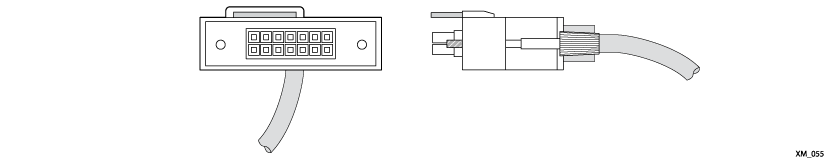
The redundant power cable has keyed ends. The key is a plastic tab
on the cable connector housing to ensure correct alignment of the connector. The
keyed ends of the 2x7 cable are not symmetrical; one end of the cable will fit into
the EPS-C2 chassis and the other end will fit into the switch.
After the EPS-C2 has been installed in a rack and the
power supplies have been installed, do the following to connect the redundant power
cables:
-
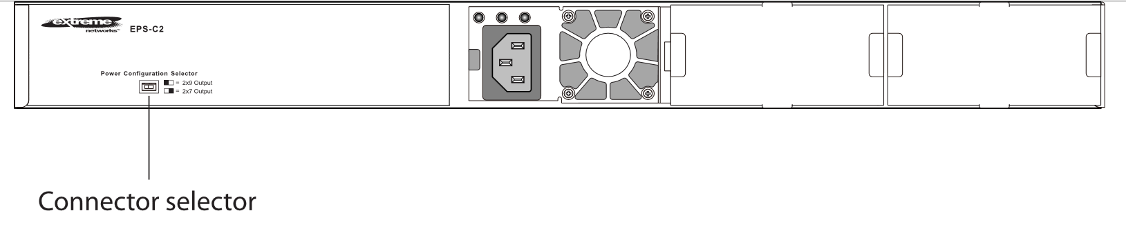
Set the connector selection switch, located on the
front of the EPS-C2 chassis, for the 2x7 connector.
-
Connect the keyed end (for the 2x7 connector
cable, the end with the tab offset from the edge of the connector pins) of the
redundant power cord to the EPS-C2 chassis.
-
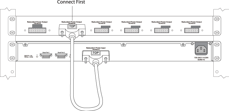
Verify that the side of the connector marked TOP
is facing up.
-
Connect the other end of the
redundant power cable (for the 2x7 connector cable, the end with the key flush
with the edge of the connector pins) to the switch.
See
Installing the Redundant Power Cord.
Be sure that the side of the connector marked TOP is facing
up.
Installing the
Redundant Power Cord

Note
The EPS-C2 2x9 connector, shown in the
figure to the left of where the cable is connected, is used only with older
switch models that are not compatible with
ExtremeXOS
version 21.1 and later.
-
Repeat the preceding steps to connect any
additional redundant power cords.
 Print
this page
Print
this page Email this topic
 Feedback
 View PDF
 Download EPUB