When performing this task, observe all of the precautions listen in Safety Considerations for Installing Power Supplies.
The redundant power supply is connected to a switch using a 1-meter RPS cable.

Note
No change in switch configuration is necessary for this installation.See the following figures.
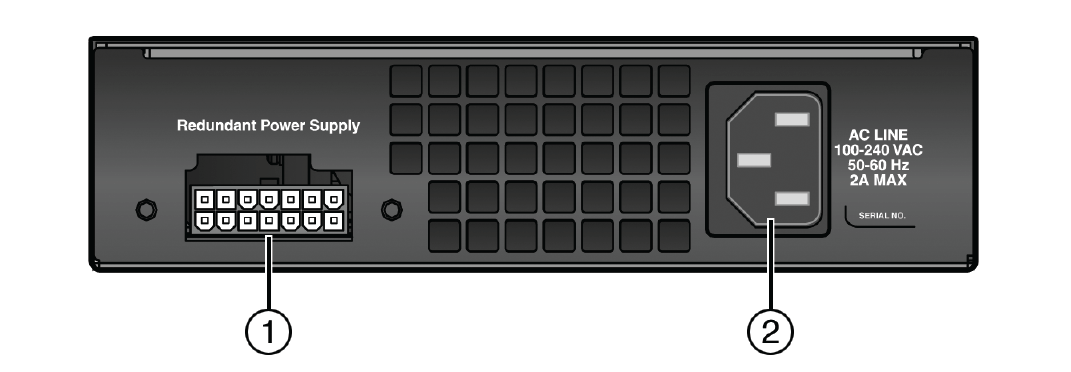
| 1 = Redundant power supply connector | 2 = AC power connector |
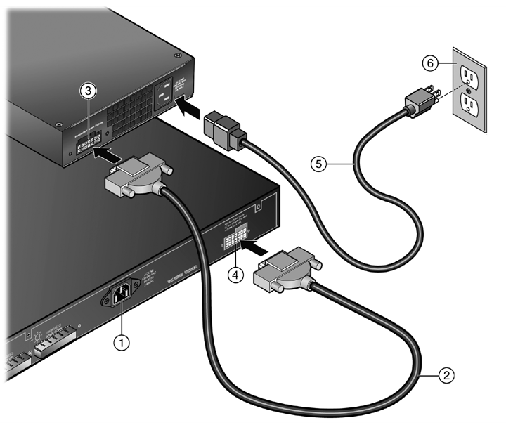
| 1 = Switch | 4 = Switch Redundant Power Supply connector (location varies depending upon switch) |
| 2 = High speed RPS cable (1 meter) | 5 = AC power cord (type varies depending on country) |
| 3 = RPS Redundant Power Supply connector | 6 = AC power outlet with ground connection (type varies depending on country) |
The green Power LED on the front of the RPS will illuminate to indicate a successful connection. On certain switches, an LED indicator on the switch will show that a redundant power supply is now in operation.
If the green power LED is not lit, proceed as follows:
If the green LED remains off, contact Extreme Networks support.
 Print
this page
Print
this page Email this topic
 Feedback
 View PDF
 Download EPUB