The following is an example of a basic Multi-VRF configuration that uses eBGP with OSPF.
The following example topology shows a typical network that uses the Multi-VRF feature to implement Layer 3 VPNs across two directly connected (at Layer 3) Provider Edge (PE) devices. The Customer Edge (CE) devices can be any router or Layer 3 switch that is capable of running one or many dynamic routing protocols such as BGP or OSPF, or even simple static routing. In this example, we use two devices that interconnect all four CE routers with a single link between the two of them.
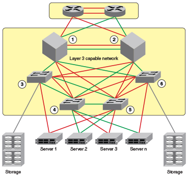
Topology details are listed below.
| Node | Description | Networks | Carries routes . . . | Interfaces |
|---|---|---|---|---|
|
PE1 |
Aggregation |
10.1.1.0/24 10.3.1.0/24 |
0/1 0/2 0/3 |
|
|
PE2 |
Aggregation |
10.2.1.0/24 10.3.1.0/24 |
0/1 0/2 0/3 |
|
|
CE1 |
Edge |
10.1.1.0/24 |
10.1.2.0/24 10.1.3.0/24 |
0/1 0/2 |
|
CE2 |
Edge |
10.1.1.0/24 |
10.1.2.0/24 10.1.3.0/24 |
0/1 0/2 |
|
CE3 |
Edge |
10.2.1.0/24 |
10.2.2.0/24 10.2.3.0/24 |
0/1 0/2 |
|
CE4 |
Edge |
10.2.1.0/24 |
10.2.2.0/24 10.2.3.0/24 |
0/1 0/2 |
The following configuration examples for PE1, PE2, CE1, CE2, CE3, and CE4 implement the topology above.

Note
The single link between the two PEs could also be replaced by a Layer 2 switched network if direct physical connection between the PEs is not possible. The only requirement for the connections is that the two PEs be directly connected at Layer 3.In the example topology, because two different VLANs (10 and 20) have overlapping IP address ranges, communication within each customer's VPN across the two PE routers (that is, between CE1 and CE4, and between CE2 and CE3) must be separated by means of two different VRFs ("green" and "red").