SLX-OS devices can act as a Layer 2 gateway.
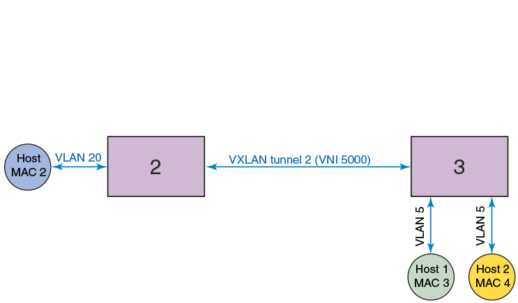
The following figure illustrates an example Layer 2 gateway topology.
| Device | IP address | Mapping |
|---|---|---|
| 1: SLX 9540 series | 1.1.1.1 | VNI 5000 < > VLAN 10 |
| 2: VDX 6740 series | 2.2.2.2 | VNI 5000 < > VLAN 20 |
| 3: SLX 9540 series | 3.3.3.3 | VNI 5000 < > VLAN 5 |
VLANs on each node are extended through common Virtual Network Instance (VNI) 5000. The MAC addresses of local hosts are learned on access points, and MAC addresses are learned on VXLAN tunnels. A split-horizon topology is supported. All nodes participating in the VLAN must be connected through VXLAN tunnels, because there is no tunnel-to-tunnel flooding of broadcast, unknown unicast, and multicast (BUM) traffic.
In this topology, Devices 1, 2, and 3 are VXLAN Layer 2 gateway devices. On Device 3, tunnel 1 and tunnel 2 are mapped to VLAN 5. VLAN 5 has two hosts, MAC 3 and MAC 4. Device 3 is connected to two other hosts, Device 1 and Device 2, which connect to hosts MAC 1 and MAC 2, respectively, through VXLAN tunnels 1 and 2, respectively. If MAC 3 needs to establish traffic to MAC 1, initially there will be BUM flooding and upon a response from MAC 1, MAC 1 is learned through tunnel 1. Subsequent traffic goes directly from MAC 3 to Device 1 on tunnel 1. Traffic in the reverse direction comes from Device 1, is decapsulated, and goes to MAC 3.