Virtual Private LAN Service (VPLS) is a Layer 2 Virtual Private Network (L2 VPN) architecture that provides multipoint Ethernet LAN services.

Note
VPLS and VLL Layer 2 VPN services are not supported on SLX 9150 series and SLX 9250 series devices.VPLS provides transparent LAN services across provider edge (PE) devices using Internet Protocol (IP) or Multiprotocol Label Switching (MPLS) as the transport technology.
Because it emulates LAN switching, VPLS is considered to be a L2 service that operates over Layer 3 (L3) clouds.
VPLS provides point-to-multipoint (p2mp) functionality while VLL is a special type of VPLS deployment that performs point-to-point (p2p) switching.
VLL is a special type of VPLS deployment that performs point-to-point switching.
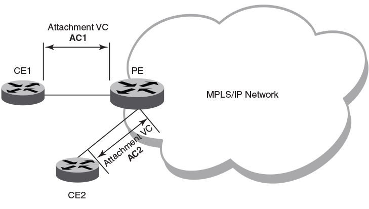
The following figure shows a VPLS topology in which switched packets traverse a network.

AC1 and AC2 represent L2 connectivity between customer edge (CE) and provider edge (PE) devices.
Pseudowire is a circuit emulation infrastructure that extends L2 connectivity from CE1 to CE2 by way of PE1 and PE2. The tunnel is typically a L3 tunnel on which a L2 circuit is emulated.
In the case of a packet flowing from CE1 to CE2, the packet enters PE1 from CE1 after the forwarding database (FDB) is used to determine the destination MAC address. Then, a virtual connection (VC) label is imposed prior to encapsulation with the tunnel forwarding information, and the packet is sent out onto the wire towards the network core.
Essentially, the topology in the preceding figure shows a L2 VPN enabling the transport of L2 traffic between two or more native Ethernet networks through an underlying Multiprotocol Label Switching (MPLS) provider network. Customer edge (CE) is the last mile and provider edge (PE) is the first mile node for packets transported towards the provider network. The provider intermediary network is an emulated switch (LAN) or wire (LINE) to the CE. The attachment circuit (AC) represents the logical link between the CE and PE.
An AC may be a port, IEEE 802.1q or IEEE 802.1ad (QinQ)) for Ethernet VPNs. A pseudowire (PW) or emulated wire is used as a transport mechanism to tunnel frames between PEs. A PW is characterized by a circuit identifier, which identifies the destination PE.
MPLS tunnels and paths are established by using routing protocols. PW circuits are established by using signaling.
The following figure shows a VPLS topology where switching occurs between two local AC endpoints. This implementation of VPLS does not use VC labels or a pseudowire.
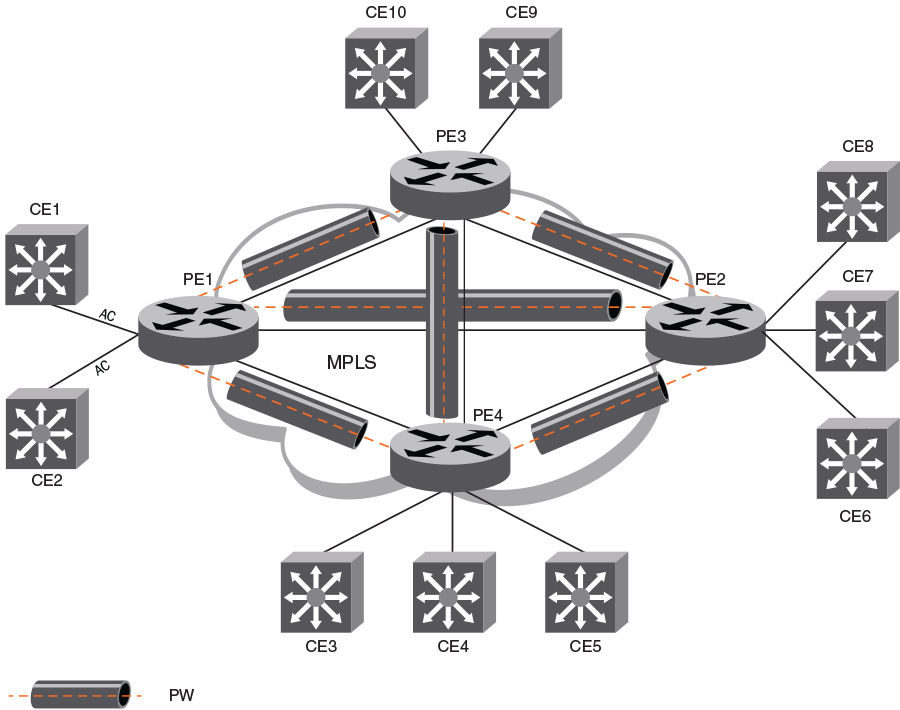
The following figure shows a common VPLS deployment; an enterprise LAN service. The CE devices represent customer edge devices while the PE devices represent provider edge devices.