Forced Switch (FS) is an operator-initiated mechanism that moves the blocking role of the RPL to a different ring link followed by unblocking the RPL, even if one or more failed links exist in the ring.
The node configured to initiate an FS blocks the port and sends out a R-APS (FS) to inform other nodes to unblock any blocked ports (including failed ones) as long as no other local request with higher priority exists. The RPL owner unblocks the RPL and flushes the FDB.
Any node accepting a R-APS (FS) message stops transmitting R-APS messages.
Multiple FS instances can be configured in the topology even when the topology is in the same segment where an FS is being cleared by no command. When an operator clears an FS on the same node where an FS is configured, this node keeps the port in the blocking state, sends out a R-APS (NR) to adjacent nodes, and starts the guard timer. Other nodes that receive the R-APS (NR) forward the message. When the RPL owner receives this message, the RPL owner starts the WTB timer. When the WTB timer expires, the RPL owner sends out a R-APS (NR, RB), blocks the RPL, and flushes the FDB. Other nodes in the topology that receive the R-APS (NR, RB) unblock any non-failed port and flush the FDB.
An FS request can be accepted no matter what state the topology is in. Since the local FS and R-APS (FS) are higher priority than SF; an SF occur i ng later than FS will not trigger the SF process. In addition, because the local FS and R-APS (FS) are higher priority than SF, when a node receives a R-APS (FS) without any local higher priority event, it will unblock any blocked port. The node with the failed link also unblocks the blocked port; but because the link has failed, the topology is broken into segments.
Since the local FS and R-APS (FS) are higher priority than a local SF clear when the link failure is removed without any local higher priority event, the nodes with the recovering link do not trigger SF recovery.
After the operator clears the FS condition on the node, the node starts the guard timer and sends out a R-APS (NR). When the RPL owner receives a R-APS(NR), it stops the WTB timer and starts the guard timer. The RPL owner blocks the RPL and sends out a R-APS (NR, RB). Any node receiving a R-APS (NR, RB) unblocks the non-failed blocked port. If the guard timer is still running on the node with previous FS, this node ignores R-APS messages until the guard timer expires. The topology is again broken into segments. After this node processes the R-APS (NR, RB), however, it unblocks the blocked node; and the topology is in a loop free state and in one segment.
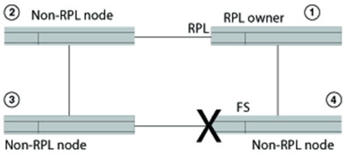
The following figure shows a port failure on ERN 4.
The following table shows the sequential order of events triggered as a result of an operator-initiated forced switch command entered from ERN 4.
|
RPL owner (ERN1) |
Non-RPL node (ERN 2) |
Non-RPL node (ERN 3) |
Non-RPL node (ERN 4) |
|---|---|---|---|
|
Idle |
Idle |
Idle |
From the Idle state, ERN 4:
|
|
From the Idle state, ERN 1:
|
From the Idle state, ERN 2:
|
From the Idle state, ERN 3:
|
|
|
From the FS state, ERN 1 forwards R-APS |
From the FS state, ERN 2 forwards R-APS |
From the FS state, ERN 3 forwards R-APS |
From the FS state, ERN 4: 7. Transmits R-APS(FS) 8. Terminates the received R-APS on the blocking port 9. Terminates its own R-APS(FS) |
|
All ERNs remain in FS state. |
|||
Next, the operator enters the no command to clear the forced switch. For this example, the operator initiated the forced switch from ERN 4 and must clear it from ERN 4. The following table shows the forced switch recovery process in sequential order.
|
RPL owner (ERN1) |
Non-RPL node (ERN 2) |
Non-RPL node (ERN 3) |
Non-RPL node (ERN 4) |
|---|---|---|---|
|
|
|
|
From the FS state, ERN 4:
|
|
From FS state, ERN 1:
|
|
|
|
|
|
From FS state, ERN 2:
|
From FS state, ERN 3:
|
|
|
After the WTB timer expires, from the Pending state ERN 1: 5. Blocks the RPL port 6. Transmits R-APS(NR,RB) 7. Unblocks the non-RPL port 8. Flushes the FDB 9. Enters the Idle state |
|
|
|
|
|
From the Pending state, ERN 2: 4. Flushes the FDB 5. Forwards R-APS(NR,RB) 6. Enters the Idle state |
From the Pending state, ERN 3: 4. Stops transmitting R-APS 5. Unblocks ports 6. Flushes the FDB 7. Forwards R-APS(NR,RB) Enters the idle state
|
From the Pending state, ERN 4: 6. Stops transmitting R-APS 7. Unblocks ports 8. Flushes the FDB 9. Forwards R-APS(NR,RB) 10. Enters the Idle state |
|
From the idle state, ERN 1: 10. Receives its own R-APS(NR,RB) 11. Stops transmitting R-APS 12. Remains in the Idle state |
|
|
|