Pseudowire (PW) control word and flow label improve PW traffic flow over a Multi-Protocol Label Switched (MPLS) packet switched network (PSN).
To ensure that a PW operates correctly over an MPLS PSN, the PW traffic is normally transported over a single network path, even when equal-cost multiple-paths (ECMPs) exist between the ingress and egress PW provider edge (PE) devices. Transporting PW traffic over a single network prevents misordered packet delivery to the egress PE device.
Because the standard MPLS label stack does not contain an explicit protocol identifier, label switching routers (LSRs) in ECMP implementations may examine the first nibble after the MPLS label stack to determine if a labeled packet is an IP packet. When the source MAC address of an Ethernet frame that is carried over a PW (without a control word present) begins with 0x4 or 0x6, it could be mistaken for an IPv4 or IPv6 packet. Depending on the configuration and topology of the MPLS network, this misinterpretation could lead to a situation in which all packets for a specific PW do not follow the same path and may increase out-of-order frames on the specific PW, or cause packets to follow a different path than actual traffic.
PW control word (RFC 4385) enables all packets for a specific PW to follow the same path over an MPLS PSN.
The following figure shows the format of the PW control word.
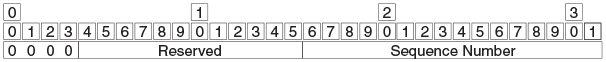
The first 4 bits are set to 0 to indicate PW data and distinguish a PW packet from an IP packet. The next 12 bits are reserved.
The last 16 bits carry a PW-specific sequence number that guarantees ordered frame delivery. A sequence number value of 0 indicates that the sequence number check algorithm is not used.

Note
PW control word is a nonconfigurable, global system value.The following figure shows the operation of PW control word in a PW over MPLS network configuration.
Pseudowire (PW) control word is configured by enabling control word for either a PW profile or for PW-related devices in a bridge domain. To enable control word for a PW profile, use the control-word command in PW profile configuration mode. To enable control word for PW-related devices in a bridge domain, use the peer command in bridge domain configuration mode.
Some PWs transport high volumes of traffic that comprise multiple separate traffic flows (for example, all packets for the same source-destination pair for a Transport Control Protocol [TCP] connection is a specific traffic flow).
To avoid latency and jitter, it is important that packets for a specific traffic flow are mapped to the same links along the path to the egress device.
PWs that carry multiple traffic flows require only the preservation of packet ordering in the context of an individual traffic flow and do not require the preservation of packet order for all traffic carried on the PW.
In normal cases, routers use source and destination IP addresses, protocol type, and TCP or UDP port numbers as keys in a load-balancing algorithm to find the appropriate outgoing interface. In MPLS networks, deep packet inspection may be needed for LSRs to identify such keys.
PW flow label is a mechanism that supports load balancing in an MPLS network, without the need for deep packet inspection by LSRs.
The PW flow label is added to the bottom of the label stack, by the ingress LSR (which has complete information about the packet) before it pushes the label stack. Transit LSRs can use the entire label stack (including the flow label) as a key for a load-balancing algorithm.
The PW flow label allows PWs to leverage the availability of, for example, equal-cost multiple-path (ECMP) between LSRs in an MPLS PSN. The ingress PE device maps individual traffic flows within a PW to the same flow label. Label Distribution Protocol (LDP) uses the PW flow label to map packets for a specific traffic flow to the same links along the path and to ensure that packets for the specific traffic flow follow the same path over the MPLS PSN. The PW flow label is discarded at the egress PE device.
Note
PW flow label load balancing is not supported when the incoming packet contains more than three labels.The following figure shows packet encapsulation when flow label is enabled for PW traffic.
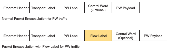
PW flow label is not a reserved value (that is, in the range from 0 through 15). To prevent any processing of flow label at the egress LSR, the TTL value of the flow label is set to 0.
Note
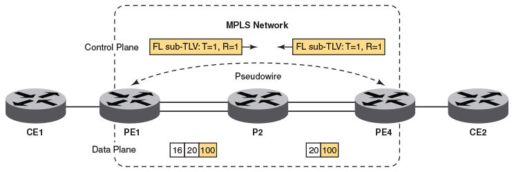
PW flow label is not signaled between PE routers. The flow label is generated locally and pushed to the bottom of the stack by the ingress LSR.The following figure, which shows a PW over MPLS network configuration, describes the operation of PW flow label.
Note
When load balancing is based only on PW flow label, the transit device (P2) must be configured to include the bottom-of-stack (BOS) label by using the lag hash bos start command.Pseudowire (PW) flow label is configured either by enabling flow label either for a PW profile or the bridge domain to which the PW is attached.
Pseudowire (PW) flow label is configured by enabling flow label for either a PW profile or PW-related devices in a bridge domain. To enable flow label for a PW profile, use the flow-label command in PW profile configuration mode. To enable flow label for PW-related devices in a bridge domain, use the peer command in bridge domain configuration mode.