This use case addresses an example of a network deployment by an Internet Service Provider where the port on the customer edge (CE) device is connected over a point-to-point link with a provider edge (PE) device that connects to the core network through a network edge (NE) device.
The NE device could be connected to another NE device of a core network of another ISP or its own core network on a different geographical location through an international link on a WAN. The NE device on the remote side would connect to the remote PE device to which the remote CE devices are connected.
The two PE devices that form an Ethernet virtual circuit (EVC) are connected through a Down MEP link. Now the CE devices on both local and remote sites form the client for the respective PE devices, and the connecting ports on these PE devices to the respective CE devices on local and remote sites are the designated Ethernet client ports. These client ports can be either physical interfaces or port-channel interfaces. Only one client port can be associated with an MEP. Thus, the scale for the client ports that can be associated to MEPs with a one-to-one mapping is limited by the number of MEPs that can be configured (currently 8 k) on the device, a number that is large enough compared to the total number of physical interfaces available on the device. Hence there is practically no limit to the number of ETH-CSF client ports that can be created on a device.

Note
For a discussion of MEP and other connectivity fault management (CFM) issues, see the chapter "802.1ag Connectivity Fault Management" in the Extreme SLX-OS Layer 2 Switching Configuration Guide.The purpose of the feature is to propagate the ETH-CSF indication from an MEP configured on the PE device to the remote MEP on the peer PE device when a port on CE device connected to this PE device goes down. Thus, the MEP on the PE device detects a link failure event on its ingress Ethernet client port and propagates this client signal fault to the RMEP on the remote peer PE side. The following figure illustrates an example topology.
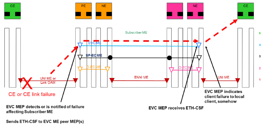
Upon reception of the CSF indication at the RMEP on the peer side, this fault signal is further propagated to the egress Ethernet client port by operationally bringing the port down. Because the CE device is connected directly to the remote PE device through a point-to-point link, the remote CE device detects an Ethernet link failure on its connected port, and the admin can take necessary actions immediately to restore the connectivity between the CE devices.
This feature is specifically helpful when the client itself (the CE device) does not support any means of notification to its peer (the remote CE device), such as through ETH-AIS or the RDI function of ETH-CC.