VPLS can be configured with switching between attachment circuits (ACs) and the network core. Because VPLS emulates LAN switching, it is considered to be a Layer 2 (L2) service that operates over Layer 3 (L3) clouds.
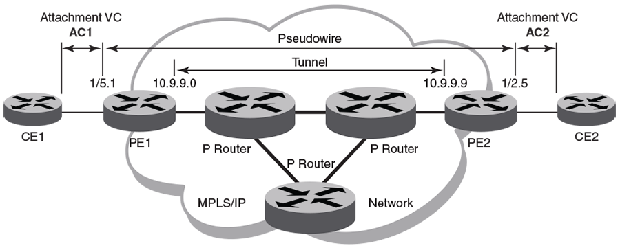
The topology in the preceding figure shows a L2 VPN that enables transport of L2 traffic between two or more native Ethernet networks through an underlying Multiprotocol Label Switching (MPLS) provider network. Customer edge (CE) is the last mile and provider edge (PE) is the first mile node for packets transported towards the provider network. The provider intermediary network is an emulated switch (LAN) or wire (LINE) to the CE. The AC represents the logical link between the CE and PE.
Pseudowire is a circuit emulation infrastructure that extends L2 connectivity from CE1 to CE2 by way of PE1 and PE2. The tunnel is typically a L3 tunnel on which a L2 circuit is emulated.
The following examples show how to configure the provider edge devices (PE1 and PE2) shown in this topology.
device# configure terminal
device(config)# bridge-domain 500 p2mp
device(config-bridge-domain-500)# vc-id 501
device(config-bridge-domain-500)# peer 10.9.9.9 load-balance
device(config-bridge-domain-500)# logical-interface ethernet 0/5.1     ! AC1
device(config-bridge-domain-500)# exit

device(config)# pw-profile default
device# configure terminal
device(config)# bridge-domain 300 p2mp
device(config-bridge-domain-300)# vc-id 501
device(config-bridge-domain-300)# peer 10.9.9.0 load-balance
device(config-bridge-domain-500)# logical-interface ethernet 0/2.5     ! AC2
device(config-bridge-domain-500)# exit

device(config)# pw-profile default