A newly configured Version 2 ERP topology with four ERNs initializes as described in this section. The ERNs have the following roles:
ERN 2 is the RPL owner.
ERNs 1, 3, and 4 are non-RPL nodes.
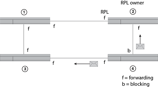
The following figure shows the first step of
initialization beginning from ERN 4, a non-RPL node.
Initializing an ERN topology - I
The actions of each ERN are as follows:
ERN 1 takes no action. Both ports are in the forwarding state.
ERN 2 (RPL owner) takes no action. Both ports, including the RPL port, are in the VLAN port forwarding state.
ERN 3 takes no action. Both ports are in the forwarding state.
From the Init state ERN 4 stops all timers (guard, WTR, WTB), blocks the left port, unblocks the right port, transmits R-APS (NR) messages, and enters the Pending state.
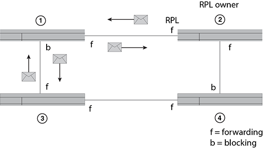
The following figure shows the next sequence
of events. Next, ERN 1 initializes.
Initializing an ERP topology -
II
The actions of each ERN are as follows:
ERN 1 stops all timers (guard, WTR, WTB), blocks the left port, unblocks the right port, transmits R-APS (NR) messages, and enters the Pending state.
ERN 2 takes no action. Both ports are in the forwarding state.
ERN 3 takes no action. Both ports are in the forwarding state.
ERN 4 stays in the Pending state, transmits R-APS (NR) messages, and continues to block the left interface.
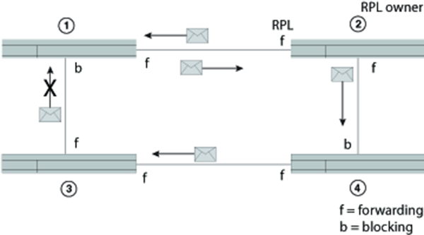
The following figure shows the next sequence
of events.
Initializing an ERP topology -
III
The actions of each ERN are as follows:
ERN 1 terminates R-APS received on the blocked port, unblocks the non-failed port, stops transmitting R-APS (NR) messages, and enters the Pending state.
ERN 2 takes no action.
ERN 3 takes no action.
ERN 4 stays in the Pending state and transmits R-APS (NR) messages.
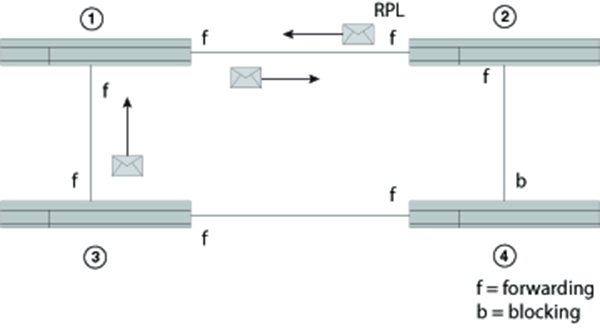
The following figure shows the next sequence
of events.
Initializing an ERP topology -
IV
The actions of each ERN are as follows:
ERN 1, from the Pending state, unblocks the left interface, stops sending R-APS (NR) and stays in the Pending state. Now both interfaces are in the forwarding state.
ERN 2 takes no action.
ERN 3 takes no action.
ERN 4 stays in the Pending state and transmits R-APS (NR) messages. The left interface is blocked, and the right interface is in the forwarding state.
The following figure shows the next sequence
of events. Next ERN 2 initializes.
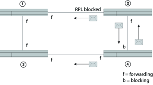
Initializing an ERP topology - V
The actions of each ERN are as follows:
ERN 1 stays in the Pending state.
ERN 2 (RPL owner), from the Init state, stops the guard timer, stops the WTB timer, blocks the RPL, unblocks the non-RPL port, enters the Pending state, transmits R-APS (NR) messages, and starts the WTR timer.
ERN 3 takes no action.
ERN 4 stays in the Pending state and transmits R-APS (NR) messages. The left interface is blocked.
The following figure shows the next sequence
of events.
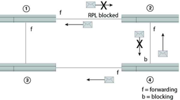
Initializing an ERP topology -
VI
The actions of each ERN are as follows:
After the WTB timer expires, ERN 2 (RPL owner in the Pending state) transmits R-APS (NR, RB), and then ERN 2 enters the Idle state.
ERN 1, still in the Pending state, forwards R-APS (NR, RB) and enters the Idle state.
ERN 3 takes no action.
ERN 4 from the Pending state and stops transmitting R-APS (NR).
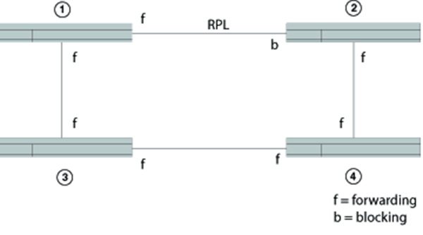
Lastly, ERNs 1, 2, and 3 are in the Idle
state, and ERN 4 changes the blocking port to the forwarding state. All ERNs remain in the
Idle state. Refer to the following figure.