Layer 3 routing is supported for IPv4 and IPv6 BGP, OSPF, and IS-IS routing protocols on an MCT VLAN or bridge domain (BD). All local and remote Layer 3 devices appear logically on the same VLAN or BD.
The following diagram is the Layer 3 MCT data plane.
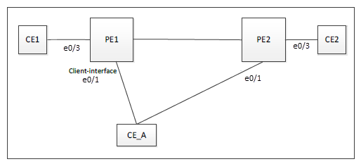
All devices are on the same VE and receive protocol Hello packets. Over the ICL link, the following packets are flooded:
Any two devices have direct Layer 3 communications.
You must first create the VE interface for the MCT VLAN or bridge domain on the MCT pair.
Enabling L3 protocols is the same as enabling them on a VE interface.
For routes learned over Layer 3 protocols, the next-hop IP address is usually the peer IP address and not necessarily the MCT router address.
To bind the VE interface to an MCT VLAN or bridge domain, use the router-interface ve command under VLAN or bridge-domain configuration mode, respectively. The following example shows how to bind VE 200 to bridge domain 2.
device# configure terminal
device(config)# bridge-domain 2
device(config-bridge-domain-2)# router-interface ve 200

Note
Where supported, MPLS cannot be enabled for a VE over an MCT VLAN interface.The following configuration example shows how to enable OSPFv2 and OSPFv3 protocols on PE1, PE2, and CE_A over VE 200 for the MCT member VLAN 2.
PE1:
router ospf
  area 0

ipv6 router ospf
  area 0

vlan 2
 router-interface Ve 200

interface Ve 200
 ipv6 address 2001::1/64
 ip address 10.2.2.1/24

 ip ospf area 0
 ipv6 ospf area 0
 !
 no shutdown
!
PE2:
router ospf
  area 0

ipv6 router ospf
  area 0

vlan 2
 router-interface Ve 200

interface Ve 200
 ipv6 address 2001::2/64
 ip address 10.2.2.2/24

 ip ospf area 0
 ipv6 ospf area 0
 !
 no shutdown
!
CE_A:
router ospf
  area 0

ipv6 router ospf
  area 0

vlan 2
 router-interface Ve 200

interface Ve 200
 ipv6 address 2001::10/64
 ip address 10.2.2.10/24

 ip ospf area 0
 ipv6 ospf area 0
 !
 no shutdown
!
The following configuration example shows how to enable OSPFv2 and OSPFv3 protocols on PE1, PE2, and CE_A over VE 200 for the MCT member bridge-domain 2.
PE1:
router ospf
  area 0

ipv6 router ospf
  area 0

interface Ve 200
 ipv6 address 2001::1/64
 ip address 10.2.2.1/24
!
 ip ospf area 0
 ipv6 ospf area 0
 !
 no shutdown

bridge-domain 2 p2mp
 router-interface Ve200
 logical-interface ethernet 0/1.2
 pw-profile default
 bpdu-drop-enable
 local-switching
!
PE2:
router ospf
  area 0

ipv6 router ospf
  area 0

interface Ve 200
 ipv6 address 2001::2/64
 ip address 10.2.2.2/24
!
 ip ospf area 0
 ipv6 ospf area 0
 !
 no shutdown

bridge-domain 2 p2mp
 router-interface Ve200
 logical-interface ethernet 0/1.2
 pw-profile default
 bpdu-drop-enable
 local-switching
!
CE_A:
router ospf
  area 0

ipv6 router ospf
  area 0

interface Ve 200
 ipv6 address 2001::10/64
 ip address 10.2.2.10/24
!
 ip ospf area 0
 ipv6 ospf area 0
 !
 no shutdown

bridge-domain 2 p2mp
 router-interface Ve200
 logical-interface ethernet 0/1.2
 pw-profile default
 bpdu-drop-enable
 local-switching

!