
Note
This topology is for only one BD. Since the DF state is selected per BD, another BD can use a different PE as the active node.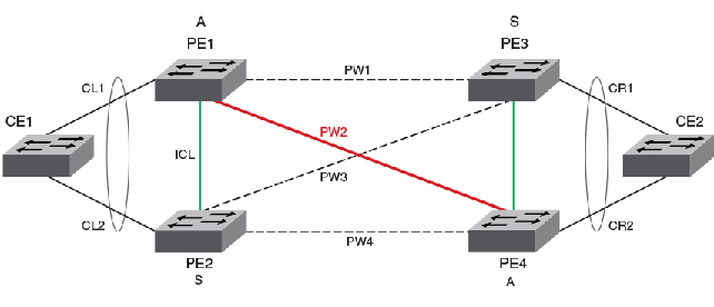
When VLL MCT is activated, only one PW is operationally active between the MCT clusters, as represented by the solid line. The standby PWs are represented by the dotted lines.
The ICL link between the MCT nodes is a VxLAN tunnel.
Note
VLL MCT does not use MAC learning. BUM traffic handling is not required. It uses cross-connect instead of VSI.Based on the previous figure, the steady state traffic is as follows:
When the client link (CL1) is down, the device does not change the MCT status for this VLL. Traffic from the client will be received on CL2 to PE2 and forwarded using the VxLAN tunnel from PE2 to PE1. The traffic flow from the client is as follows:
VLL MCT provides protection when one PE node has a failure including a software or hardware failure, or a power down. In the case when the active MCT node (PE1) is down, the standby MCT node acts as active and uses corresponding PWs for the traffic flow from the client. The traffic flow from the client is as follows:
Note
For active-active PW link protection when the PW redundancy status changes, the device relies on the MPLS configuration. There should not be a case where PW2 is down and PW4 is up. The configuration ensures that both PW2 and PW4 are UP or DOWN. When PW2 is not active-active due to a role change on PE4, PW1 will become active-active.