To edit or apply overrides to an Ethernet port configuration:
|
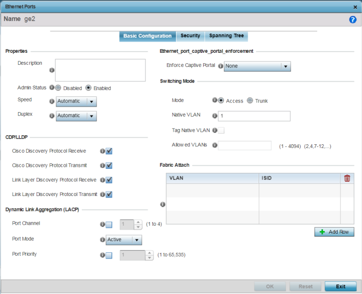
Description |
Enter a brief description for the port (64 characters maximum). The description should reflect the port‘s intended function to differentiate it from others with similar configurations, or it simply can be the name of the physical port. |
|
Admin Status |
Select Enabled to define this port as active to the profile it supports. Select Disabled to disable this physical port in the profile. It can be activated at any time when needed. Admin status is enabled by default. |
|
Speed |
Select the speed at which the port can receive and transmit data, to establish a 10, 100, or 1000 Mbps data transfer rate for the selected half-duplex or full-duplex transmission. These options are not available if Automatic is selected. Select Automatic to enable the port to automatically exchange information about data transmission speed and duplex capabilities. Auto negotiation is helpful when in an environment where different devices are connected and disconnected on a regular basis. Automatic is the default setting. |
|
Duplex |
Select either Half, Full, or Automatic as the duplex option. Select Half duplex to send data over the port, then immediately receive data from the same direction in which the data was transmitted. Like a full-duplex transmission, a half-duplex transmission can carry data in both directions, just not at the same time. Select Full duplex to transmit data to and from the port at the same time. Using full duplex, the port can send data while receiving data as well. Select Automatic to enable to the controller or service platform to dynamically duplex as port performance needs dictate. Automatic is the default setting. |
|
Cisco Discovery Protocol Receive |
Select this option to allow the Cisco discovery protocol for receiving data on this port. If enabled, the port sends out periodic interface updates to a multicast address to advertise its presence to neighbors. |
|
Cisco Discovery Protocol Transmit |
Select this option to allow the Cisco discovery protocol for transmitting data on this port. If enabled, the port sends out periodic interface updates to a multicast address to advertise its presence to neighbors. |
|
Link Layer Discovery Protocol Receive |
Select this option to allow the Link Layer discovery protocol to be received on this port. If enabled, the port sends out periodic interface updates to a multicast address to advertise its presence to neighbors. This option is enabled by default. |
|
Link Layer Discovery Protocol Transmit |
Select this option to allow the Link Layer discovery protocol to be transmitted on this port. If enabled, the port sends out periodic interface updates to a multicast address to advertise its presence to neighbors. |
|
Port Channel |
Select to configure the selected port as a member of a LAG (link aggregation group). Link aggregation is supported only on the following platforms: LACP enables combining and managing multiple physical connections like Ethernet ports as a single logical channel as defined in the IEEE 802.1ax standard. LACP provides redundancy and increase in throughput for connections between two peers. It also provides automatic recovery in cases where one or more of the physical links - making up the aggregation - fail. Similarly, LACP also provides a theoretical boost in speed compared to an individual physical link. Note:
if enabling LACP, disable or physically disconnect interfaces that do not use spanning tree to prevent loop formation until LACP is fully configured on both the local and remote devices. |
|
Port Mode |
Set the port mode as Active or Passive. If setting the port as a LAG member, specify whether the port is an active or passive member within the group. An active member initiates and participates in LACP negotiations. It is the active port that always transmits LACPDU irrespective of the remote device‘s port mode. The passive port only responds to LACPDU received from its corresponding active port. At least one port within a LAG, on either of the two negotiating peers, should be in the active mode. LACP negotiations are not initiated if all LAG member ports are passive. Further, the peer-to-peer LACP negotiations are always initiated by the peer with the lower system-priority value. |
|
Port Priority |
Select this option and set the selected Ethernet Port‘s priority value, within the LAG, from 1-65535. The selected port‘s actual priority within the LAG is determined by the port-priority value specified here along with the port‘s number. Higher the value, lower is the priority. Use this option to manipulate a port‘s priority. For example, in a LAG having five physical ports, four active and one standby, manually increasing the standby port‘s priority ensures that if one of the active port fails, the standby port is included in the LAG during re-negotiation. |
|
None |
Select to prevent captive-portal access permission rules to be enforced. |
|
Authentication Failure |
Select to apply captive-portal access permission rules only when user authentication fails. |
|
Always |
Select to enforce captive-portal access permissions at all times. |
|
Mode |
Set the VLAN switching mode over the port. The options are: Access - select to enable the port accept packets only from the native VLAN. Frames are forwarded untagged with no 802.1Q header. All frames received on the port are expected as untagged and mapped to the native VLAN. This is the default setting. Trunk - select to enable the port allow packets from a list of VLANs you add to the trunk. The port supports multiple 802.1Q tagged VLANs and one native VLAN which can be tagged or untagged. |
|
Native VLAN |
Define a VLAN ID (1 - 4094) for the native VLAN. The native VLAN allows an Ethernet device to associate untagged frames to a VLAN when no 802.1Q frame is included in the frame. Additionally, the native VLAN is the VLAN over which untagged traffic is directed when using a port in Trunk mode. The default VLAN is 1. |
|
Tag Native VLAN |
Select this option to tag the native VLAN. Controller and service platforms support the IEEE 802.1Q specification for tagging frames and coordinating VLANs between devices. IEEE 802.1Q adds four bytes to each frame identifying the VLAN ID for upstream devices that the frame belongs. If the upstream Ethernet device does not support IEEE 802.1Q tagging, it does not interpret the tagged frames. When VLAN tagging is required between devices, both devices must support tagging and be configured to accept tagged VLANs. When a frame is tagged, the 12 -bit frame VLAN ID is added to the 802.1Q header so upstream Ethernet devices know which VLAN ID the frame belongs to. The device reads the 12 bit VLAN ID and forwards the frame to the appropriate VLAN. When a frame is received with no 802.1Q header, the upstream device classifies the frame using the default or native VLAN assigned to the Trunk port. The native VLAN allows an Ethernet device to associate untagged frames to a VLAN when no 802.1Q frame is included in the frame. This feature is disabled by default. |
|
Allowed VLANs |
Selecting Trunk as the mode enables the Allowed VLANs parameter. Add VLANs that exclusively send packets over the listed port. |

Note
To enable FA Client feature, the Ethernet port‘s switching mode should be set to trunk.
|
VLAN |
Set the VLAN from 1 - 4094. |
|
ISID |
User the spinner control to specify the ISID from 1 - 16777214. This is the ISID (Individual Service Identifier) associated with the VLAN interface specified above. Configuring a VLAN to ISID assignment, enables FA client operation on the selected Ethernet port. The FA Client requests acceptance of the VLAN to ISID mapping from the FAS within the FC (Fabric Connect) network. Once acceptance is achieved, the FC edge switch applies the ISID to the VLAN traffic from the device (AP or controller), and uses this ISID inside the Fabric. Note:
A maximum of 94 pairs of I-SID to VLAN mappings can be configured per Ethernet port. |
FA-enabled switches, in the FC network, send out LLDP messages with TLV extensions of Organization-specific TLV with OUI, to discover FA clients and advertise capabilities.
The FA-enabled client associates with the FAS (FA Server), and obtains provisioning information (management VLAN interface details, and whether the interface is tagged or not) that allows the client to be configured with parameters that allow traffic to flow through the Fabric to the WLAN controller. Use this option to configure the ISID to VLAN mapping that the FA Client uses to negotiate with the FAS.
You can configure FA Client capability on a device‘s profile as well as device contexts.
Click Reset to revert to the last saved configuration.
 Print
this page
Print
this page Email this topic
 Feedback
 View PDF
 Download EPUB