Use RF Domain Overrides to define settings overriding a target device‘s original RF Domain configuration. An RF Domain allows an administrator to assign configuration data to multiple access points (of the same model) deployed in a common coverage area (floor, building or site). In such instances, there are many configuration attributes these devices share as their general client support roles are quite similar. However, device configurations may need periodic refinement from their original RF Domain administered design. Unlike a RFS series controller, an access point supports a single RF domain. An access point RF Domain cannot be used on a different model access point. For example, an AP 6532 RF Domain override can only be applied to another AP 6532 model access point.
The Device Overrides screen displays. This screen lists devices within the managed network.
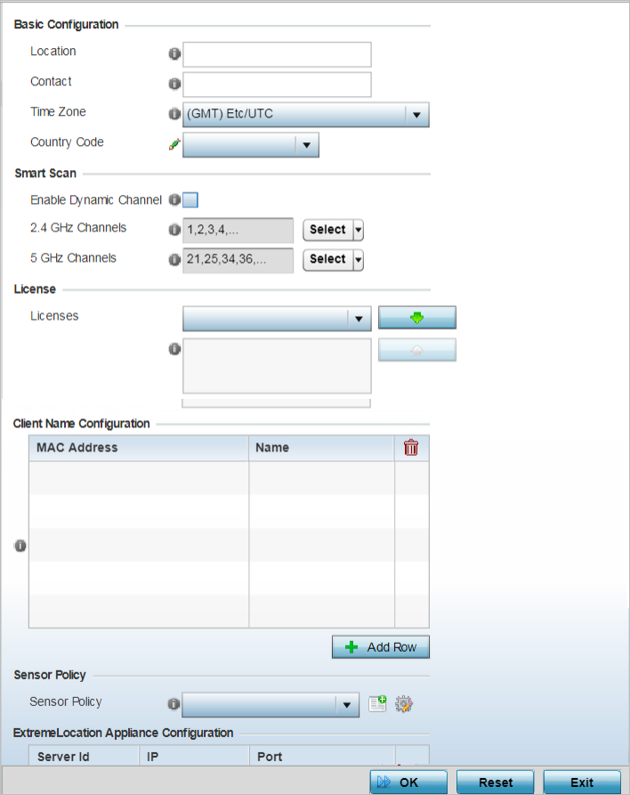
The selected access point's configuration menu displays, with the Basic configuration screen selected by default.
The RF Domain configuration overrides screen displays.

Note
A blue override icon (to the left of a parameter) defines the parameter as having an override applied. To remove a device‘s override, go to the Basic Configuration screen‘s Device Overrides field, and then select the Clear Overrides button.
|
Location |
Set the deployment location for the access point as part of its RF Domain configuration |
|
Contact |
Set the administrative contact for the access point. This should reflect the administrator responsible for the access point‘s configuration and wireless network. |
|
Time Zone |
Use the drop-down menu to select the geographic time zone supporting its deployment location |
|
Country Code |
Use the drop-down menu to select the country code supporting its deployment location |
|
Enable Dynamic Channel |
Select this option to enable dynamic channel scan. |
|
2.4 GHz Channels |
Use the Select drop-down menu to select channels to scan in the 2.4 GHz band. Selected channels are highlighted with a grey background. Unselected channels are highlighted with a white background. Multiple channels can be selected at the same time |
|
5.0 GHz Channles |
Use the Select drop-down menu to select channels to scan in the 5.0 GHz band. Selected channels are highlighted with a grey background. Unselected channels are highlighted with a white background. Multiple channels can be selected at the same time |
Enter the client‘s factory coded MAC address in the MAC Address field. Assign a name to the RF Domain member access point‘s connected client to assist in its easy recognition in the Name field.
Note
If a dedicated sensor is utilized with WIPS for rogue detection, any sensor policy selected from the Sensor Policy drop-down menu is discarded and not utilized by the sensor. To avoid this situation, use ADSP channel settings exclusively to configure the sensor and not the WiNG interface.
Select the Create icon to create a new sensor policy to apply to this RF Domain or select the Edit icon to update the configuration of an existing policy before applying it to the RF Domain. For more information, see Sensor Policy.
|
Server Id |
Use the spinner control to assign a numeric ID for up to three ExtremeLocation servers designated to receive RSSI scan data from a WiNG dedicated server. The server with the lowest defined ID is the first reached. The default ID is 1. |
|
IP Address/Hostname |
Provide the numeric (non DNS) IP address or hostname of up to three ExtremeLocation server resources for receiving RSSI scan data. A hostname cannot exceed 64 characters or contain an underscore. |
|
Port |
Use the spinner control to specify the port of the ExtremeLocation sensor server resource receiving RSSI scan data from a dedicated sensor. The default port is 443. |
Click Reset to revert to the last saved configuration.
 Print
this page
Print
this page Email this topic
 Feedback
 View PDF
 Download EPUB