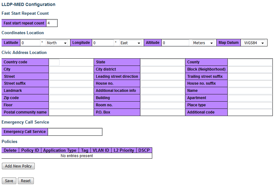
This page allows you to configure the LLDP-MED. This function applies to VoIP devices which support LLDP-MED.
| Object | Description |
|---|---|
| Fast start repeat count | |
| Fast start repeat count | Rapid startup and Emergency Call Service Location Identification Discovery of endpoints is a critically important aspect of VoIP systems in general. In addition, it is best to advertise only those pieces of information which are specifically relevant to particular endpoint types (for example only advertise the voice network policy to permitted voice-capable devices), both in order to conserve the limited LLDPU space and to reduce security and system integrity issues that can come with inappropriate knowledge of the network policy. With this in mind LLDP-MED defines an LLDP-MED Fast Start interaction between the protocol and the application layers on top of the protocol, in order to achieve these related properties. Initially, a Network Connectivity Device will only transmit LLDP TLVs in an LLDPDU. Only after an LLDP-MED Endpoint Device is detected, will an LLDP-MED capable Network Connectivity Device start to advertise LLDP-MED TLVs in outgoing LLDPDUs on the associated port. The LLDP-MED application will temporarily speed up the transmission of the LLDPDU to start within a second, when a new LLDP-MED neighbor has been detected in order share LLDP-MED information as fast as possible to new neighbors. Because there is a risk of an LLDP frame being lost during transmission between neighbors, it is recommended to repeat the fast start transmission multiple times to increase the possibility of the neighbors receiving the LLDP frame. With Fast start repeat count it is possible to specify the number of times the fast start transmission would be repeated. The recommended value is 4 times, given that 4 LLDP frames with a 1 second interval will be transmitted, when an LLDP frame with new information is received. It should be noted that LLDP-MED and the LLDP-MED Fast Start mechanism is only intended to run on links between LLDP-MED Network Connectivity Devices and Endpoint Devices, and as such does not apply to links between LAN infrastructure elements, including Network Connectivity Devices, or other types of links. |
| Coordinates Location | |
| Latitude | Latitude SHOULD be normalized to within 0 – 90 degrees with a maximum of four digits. It is possible to specify the direction to either North of the equator or South of the equator. |
| Longitude | Longitude SHOULD be normalized to within 0 – 180 degrees with a maximum of four digits. It is possible to specify the direction to either East of the prime meridian or West of the prime meridian. |
| Altitude | Altitude SHOULD be normalized to within -32767 to 32767 with a maximum of four digits. It is possible to select between two altitude types (floors or meters). Meters: Representing meters of Altitude defined by the vertical datum specified. Floors: Representing altitude in a form more relevant in buildings which have different floor-to-floor dimensions. An altitude = 0.0 is meaningful even outside a building, and represents ground level at the given latitude and longitude. Inside a building, 0.0 represents the floor level associated with ground level at the main entrance. |
| Map Datum | The Map Datum is used for the coordinates given in these options: WGS84: (Geographical 3D) - World Geodesic System 1984, CRS Code 4327, Prime Meridian Name: Greenwich. NAD83/NAVD88: North American Datum 1983, CRS Code 4269, Prime Meridian Name: Greenwich; The associated vertical datum is the North American Vertical Datum of 1988 (NAVD88). This datum pair is to be used when referencing locations on land, not near tidal water (which would use Datum = NAD83/MLLW). NAD83/MLLW: North American Datum 1983, CRS Code 4269, Prime Meridian Name: Greenwich; The associated vertical datum is Mean Lower Low Water (MLLW). This datum pair is to be used when referencing locations on water/sea/ocean. |
| Civic Address Location | |
| Country code | The two-letter ISO 3166 country code in capital ASCII letters - Example: DK, DE or US. |
| State | National subdivisions (state, canton, region, province, prefecture). |
| County | County, parish, gun (Japan), district. |
| City | City, township, shi (Japan). Example: Copenhagen. |
| City district | City division, borough, city district, ward, chou (Japan). |
| Block (Neighborhood) | Neighborhood, block. |
| Street | Street. Example: Poppelvej. |
| Leading street direction | Leading street direction. Example: N. |
| Trailing street suffix | Trailing street suffix. Example: SW. |
| Street suffix | Street suffix. Example: Ave, Platz. |
| House no. | House number. Example: 21. |
| House no. suffix | House number suffix. Example: A, 1/2. |
| Landmark | Landmark or vanity address. Example: Columbia University. |
| Additional location info | Additional location info. Example: South Wing. |
| Name | Name (residence and office occupant). Example: Flemming Jahn. |
| Zip code | Postal/ZIP code. Example: 2791. |
| Building | Building (structure). Example: Low Library. |
| Apartment | Unit (Apartment, suite). Example: Apt 42. |
| Floor | Floor. Example: 4. |
| Room no. | Room number. Example: 450F. |
| Place type | Place type. Example: Office. |
| Postal community name | Postal community name. Example: Leonia. |
| P.O. Box | Post office box (P.O. BOX). Example: 12345. |
| Additional code | Additional code. Example: 1320300003. |
| Emergency Call Service | |
| Emergency Call Service | Emergency Call Service ELIN identifier data format is defined to carry the ELIN identifier as used during emergency call setup to a traditional CAMA or ISDN trunk-based PSAP. This format consists of a numerical digit string, corresponding to the ELIN to be used for emergency calling. |
| Policies | |
| Delete | Check to delete the policy. It will be deleted during the next save. |
| Policy ID | ID for the policy. This is auto generated and shall be used when selecting the policies that shall be mapped to the specific ports. |
| Application Type | Intended use of the application types:
|
| Tag | Tag indicating whether the specified application type is using a 'tagged' or an 'untagged' VLAN. Untagged indicates that the device is using an untagged frame format and as such does not include a tag header as defined by IEEE 802.1Q-2003. In this case, both the VLAN ID and the Layer 2 priority fields are ignored and only the DSCP value has relevance. Tagged indicates that the device is using the IEEE 802.1Q tagged frame format, and that both the VLAN ID and the Layer 2 priority values are being used, as well as the DSCP value. The tagged format includes an additional field, known as the tag header. The tagged frame format also includes priority tagged frames as defined by IEEE 802.1Q-2003. |
| VLAN ID | VLAN identifier (VID) for the port as defined in IEEE 802.1Q-2003. |
| L2 Priority | L2 Priority is the Layer 2 priority to be used for the specified application type. L2 Priority may specify one of eight priority levels (0 through 7), as defined by IEEE 802.1D-2004. A value of 0 represents use of the default priority as defined in IEEE 802.1D-2004. |
| DSCP | DSCP value to be used to provide Diffserv node behavior for the specified application type as defined in IETF RFC 2474. DSCP may contain one of 64 code point values (0 through 63). A value of 0 represents use of the default DSCP value as defined in RFC 2475. |
| Adding a new policy | Click Add New Policy to add a new policy. Specify the Application type, Tag, VLAN ID, L2 Priority and DSCP for the new policy. Click Save. The number of policies supported is 32. |
| Port Policies Configuration | |
| Port | The port number to which the configuration applies. |
| Policy Id | The set of policies that shall apply to a given port. The set of policies is selected by check marking the checkboxes that corresponds to the policies. |
| Buttons | |
|---|---|
 |
Save changes. |
 |
Undo any changes and revert to previously saved values. |