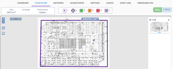
After you have your devices (APs and switches) placed on the floor plan, you can enable badges on APs, and view the heat maps and coverage using the map options and filters. For example, the RSS heat map tells you the coverage based on signal strength. The coverage percentage tells you what percent of the area is covered.
Right-click on an AP to see the Context menu, which displays links to the AP's Dashboard page, and the report about clients associated to the AP.
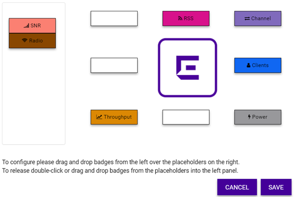
To manage badges, heat maps, and coverage:
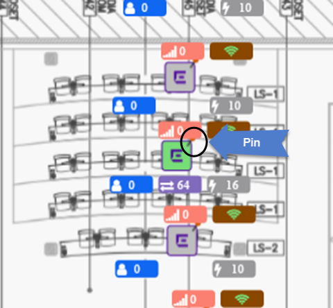
| Color | AP State |
|---|---|
| Green | In Service |
| Orange | In Service/Trouble |
| Red | Critical |
| Gray | Unknown |
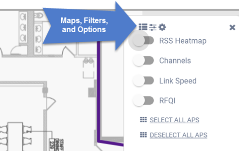
| RSS Heat Map | Shows the device coverage. Toggle between 5 Ghz and 2.4 Ghz and visualize the differences in the heat map. Colors indicate signal strength. Red indicates the strongest signal. Blue indicates the weakest signal. Heat maps are automatically recalculated when a change is detected in the device configuration. |
| Channels | Shows a visualization of the channel plan. Colors indicate primary channels for each AP, illustrating competing neighboring channels. Channels are useful for 2.4 GHz APs where neighboring APs on the same channel should be avoided. |
| Link Speed | Displays the expected internal WLAN connection speed between the wireless clients and the APs. |
| RFQI | Identifies access points with poor RF quality. The labels are color coded to indicate overall RF quality of the AP, based on the signal strength of the clients connect to them. |
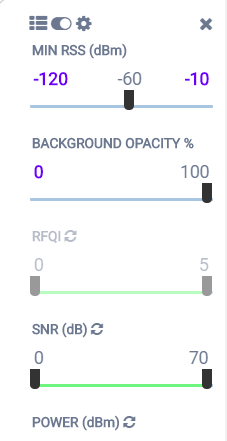
| Min RSS | Shows the APs that are within the range of the minimum received signal strength (RSS) indicated by the slider control. |
| RFQI | Shows the APs that are within the range of the radio frequency (RF) quality indicated by the slider control. |
| Power | Shows the APs that are within the range of the radio transmit power indicated by the slider control. |
| Channel | Shows the APs that are within the range of the channels indicated by the slider control. |
| Map Opacity | Makes the view of the background image more or less opaque as indicated by the slider control. |
| SNR | Shows APs that are in the range of the signal-to-noise ratio (SNR) indicated by the slider control. SNR is the ratio between the strength of the signal and the background noise on the line. This value is measure in decibels (dB). |
| Throughput | Shows the APs that are within the range of the throughput indicated by the slider control. |
| Clients | Shows the APs that are within the range of clients indicated by the slider control. The range can be from 0 - 200 clients. |
| RSS | Shows the APs that are within the range of the received signal strength, measured in dBm, indicated by the slider control. No less than three APs should be detecting and reporting the RSS of any client station. Only RSS reading stronger than -75 dBm are used by the Location Engine. |
 Print
this page
Print
this page Email this topic
 Feedback
 View PDF
 Download EPUB