As an administrator, you can make changes to your switch configuration. Use this procedure to configure an ExtremeSwitch or an Extended Edge Switch
When a configuration change is made, it gets pushed to the switch the next time the switch checks in with ExtremeCloud. If the switch does not receive a response from ExtremeCloud, the switch reboots and loads the previous working configuration that is stored on the switch.

Note
Most switch management is done using the graphical user interface (GUI). ExtremeCloud also offers a CLI mode option.To configure a switch:
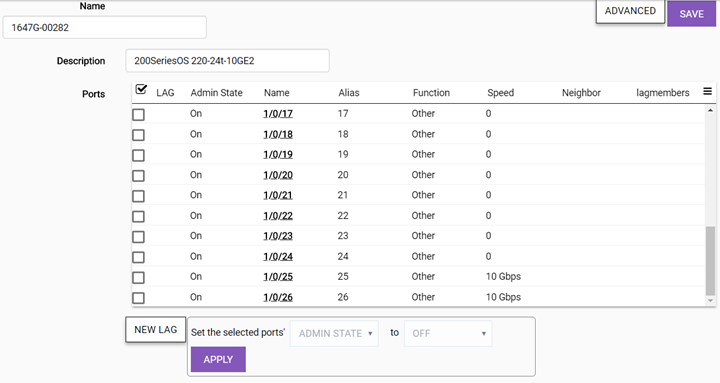
| Name | (Required) Specify a unique name. |
| Ports | Enable the check box to perform bulk configuration of ports, or select a single port from the list to configure. |
| Set Selected Ports | Select one or more ports from the list,. Then, one at a time, set the Admin State, Port Function, and PoE options to On or Off. Select Apply after each selection. |
Important
When configuring a LAG port for use by an ExtremeCloud-enabled access point, enable link aggregation on the access point first. If you do not do this, the AP can become isolated from the network. If the AP becomes isolated by the switch LAG port configuration, disable link aggregation on the switch ports used by the AP to allow the AP to join the network again. LAG can then be enabled on the AP, which takes one minute to update the configuration. Approximately two minutes later, LAG can be enabled on the corresponding switch ports.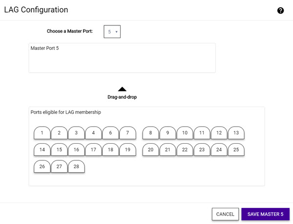
| Choose a Master Port | Specify the master port for the LAG configuration on this switch by selecting from the drop-down list. Then drag and drop the ports you want into the Master Port pane. |
Note
LLDP is automatically enabled on the switch and is not configurable. The RMA button is used for RMA replacements. For more information, see RMA Replacement Process.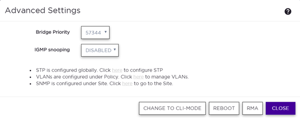
| Bridge Priority | By configuring the
STPD (Spanning Tree Domain) bridge priority, you change the
likelihood of the switch becoming the root bridge. The lower the
numerical value of the priority, the more likely the switch is the
root bridge. Multiples of 4,096 are used to determine the bridge
priority, per the 802.1D-2004 standard. Default:
Depends on the switch model. Important You should not configure this STP parameter unless you have considerable knowledge and experience with STP. The default parameter is adequate for most networks. |
| IGMP Snooping | Enable snooping of Internet Group Management Protocol (IGMP) to provide a method for intelligently forwarding multicast packets within a Layer 2 broadcast domain. By snooping the IGMP registration information, the device forms a distribution list that determines which end stations receive packets with a specific multicast address. Layer 2 switches listen for IGMP messages and build mapping tables and associated forwarding filters. IGMP snooping also reduces IGMP protocol traffic. Default: Disabled |
| LED Status | Select On to make the LEDs flash on the switch. Can be used for identifying a switch in a DC or a rack or for testing the communication between the switch and cloud management. Stays on until turned off. Default: Off |
| Change to CLI-Mode | Manage the switch in CLI mode directly from the cloud user interface. Review the CLI-Mode documentation before selecting this option. |
| Reboot | Restarts the switch. |
| RMA | Lets you replace this device with a new device and automatically assign the configuration to the new device. |
| Clone From | Use this option with an RMA switch replacement. This options lets you clone the configuration from the old switch to the new replacement switch. |
 Print
this page
Print
this page Email this topic
 Feedback
 View PDF
 Download EPUB