Configuring a Basic Topology
To configure a
basic topology:
-
From the top menu, click
VNS. Then, in
the left pane, select Topologies.
The Topologies window displays.
-
Select the topology to
edit or click New to
create a new topology.
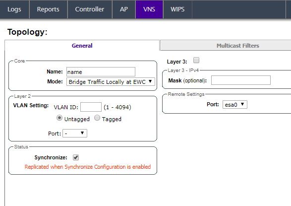
Configuring a basic topology
-
On the General tab, enter a name for
the topology in the Name field.
-
Select a mode of
operation from the Mode drop-down list. Choices
are:
- Physical —
VLAN (Virtual LAN) identifier (1 - 4094), with at least
one layer 2 member port (no mu associated).
- Routed — Routed
topologies do not require Layer 2 configuration (controller internal VLAN
identifier from valid range 1- 4094), and Layer 3 configuration. See Layer 3 Configuration for more
information.
- Bridge Traffic Locally at
AP — Requires Layer 2 configuration. Does not require Layer
3 configuration. Bridge Traffic at the AP VNSs do not require the definition
of a corresponding IP address since all traffic for users in that VNS will
be directly bridged by the Wireless AP at the local network point of
attachment (VLAN at AP port).
- Bridge Traffic Locally at
EWC
— Requires Layer 2 configuration. May optionally have Layer 3 configuration.
Layer 3 configuration would be necessary if services (such as
DHCP (Dynamic Host Configuration Protocol), captive portal, etc.) are required
over the configured network segment, or if controller management operations
are intended to be done through the configured interface.
- Fabric Attach — The Fabric Attach topology type is similar to B@AP with the added I-SID
parameter. Fabric Attach can be configured on a controller anywhere a B@AP topology can be
configured. See
Bridge Traffic Locally at AP.
-
Configure the Layer 2
VLAN Settings, depending on
the previously selected Mode.
- For Physical, enter a VLAN
identifier (2 - 4094), with at least one layer 2 member port (no MU
associated).
- For Bridge Traffic Locally at
EWC, enter a VLAN
identifier (2- 4094) that is valid for your system and enter the port to
which this VLAN is attached to, according to the networking deployment model
pre-established during planning.
- For Bridge Traffic Locally at
AP, enter a VLAN identifier (1 - 4094), 4094 is reserved for
Internal VLAN ID.
- For Fabric
Attach, enter a VLAN identifier (1 - 4094), 4094 is reserved
for Internal VLAN ID and an I-SID (service identifier).
- Specify whether the VLAN configuration is
Tagged
or
Untagged.
- To eliminate ARP Request Broadcast on the
Wireless network, select ARP
Proxy. ARP Proxy applies to traffic for Bridge Traffic Locally at
AP Topologies. ARP Proxy is configurable per
topology.
- For Port, select the Physical
(Ethernet) or LAG (Link Aggregation Group) data port. For more
information, see Viewing and Changing the L2 Ports Information.
-
(Optional) Provide a netmask in the Mask field for
topologies that do not support Layer 3. This option makes it possible to add the
Framed-IP-Netmask attribute to the client RADIUS accounting
request packets when the topology does not support Layer 3.
-
Click Save to save your
changes.
These steps are
sufficient to create and save a topology. The following configuration options are
optional and depend on the mode of the topology.
 Print
this page
Print
this page Email this topic
 Feedback
 View PDF
 Download EPUB