Using SNMP to Configure VLAN Routing
While setting the IP address for the VLAN interface, the agentSwitchIpInterfaceIpAddress
and agentSwitchIpInterfaceNetMask should be set together.
- VLAN index 482 (VLAN 10): 192.150.3.1 255.255.255.0
- VLAN index 483 (VLAN 20): 192.150.4.1 255.255.255.0
-
Use the dot1qVlanStaticRowStatus object in the dot1qVlanStaticTable to create VLAN 10 and VLAN 20.
-
To configure VLAN membership, retrieve the current dot1qStaticEgressPorts mask and append the desired interfaces to the mask.
- VLAN 10: 1/0/1 and 1/0/2
- VLAN 20: 1/0/3
-
To assign the PVID for an interface, use the dot1qPvid object.
- 1/0/1: PVID 10
- 1/0/2: PVID 10
- 1/0/3: PVID 20
-
To specify that all frames transmitted for VLANs 10 and 20 will be tagged, use the dot1qVlanStaticUntaggedPorts object and set the value of the appropriate number of octets to 0.
Each octet represents eight ports, so for a 48-port switch, the first six octets would be zero.
-
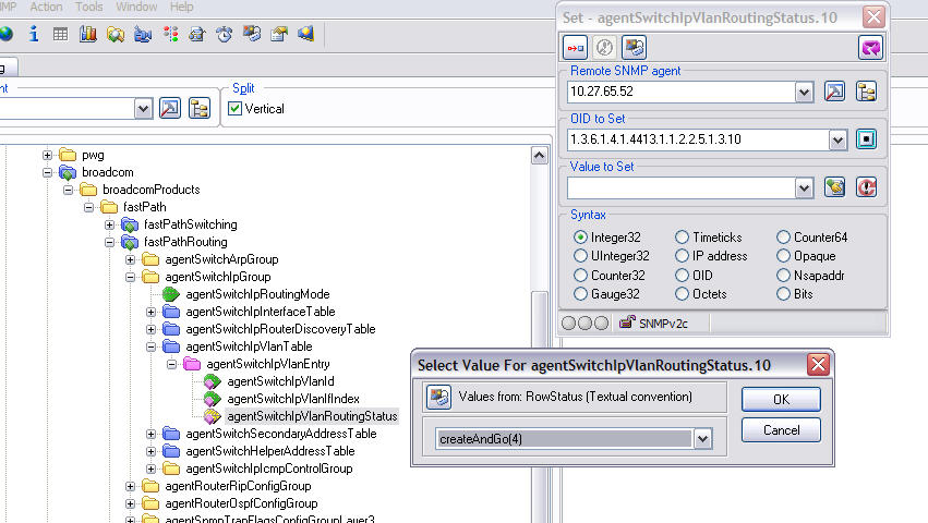
To enable routing for the VLANs, use the agentSwitchIpVlanRoutingStatus object in the agentSwitchIpVlanTable under agentSwitchIpGroup in fastPathRouting to set the value for VLAN 10 and VLAN 20 to CreateAndGo (4).
-
Walk the agentSwitchIpVlanIfIndex object to view the logical interface IDs assigned to the VLAN routing interfaces.
-
Set the agentSwitchIpRoutingMode object to enable (1) to enable routing for the switch:
-
Use the agentSwitchIpInterfaceIpAddress and agentSwitchIpInterfaceIpMask objects in the agentSwitchIpInterfaceTable to configure the IP addresses and subnet mask for the virtual router ports.
 Print
this page
Print
this page Email this topic
 Feedback
 View PDF
 Download EPUB