Traffic Flow Diagram illustrates a simple configuration with a single controller and two APs, each supporting a wireless device. A RADIUS server on the network provides authentication, and a DHCP (Dynamic Host Configuration Protocol) server is used by the APs to discover the location of the controller during the initial registration process. Network inter-connectivity is provided by the infrastructure routing and switching devices.
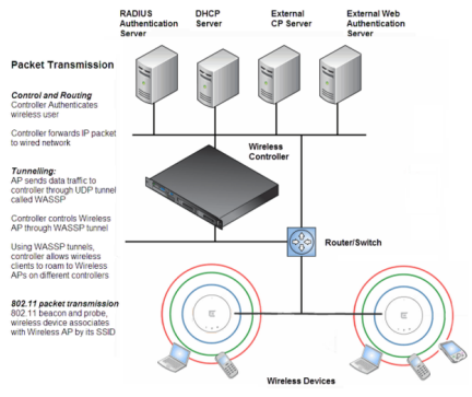
Each wireless device sends IP packets in the 802.11 standard to the AP. The AP uses a UDP (User Datagram Protocol) based tunnelling protocol. In tunneled mode of operation, it encapsulates the packets and forwards them to the controller. The controller decapsulates the packets and routes these to destinations on the network. In a typical configuration, access points can be configured to locally bridge traffic (to a configured VLAN (Virtual LAN)) directly at their network point of attachment.
The controller functions like a standard L3 router or L2 switch. It is configured to route the network traffic associated with wireless connected users. The controller can also be configured to simply forward traffic to a default or static route if dynamic routing is not preferred or available.
 Print
this page
Print
this page Email this topic
 Feedback
 View PDF
 Download EPUB