Viewing and Changing the L2 Ports Information
To view and change the l2 port
information:
-
From the top menu, click
Controller.
- In the left pane, click . The L2 Ports tab is displayed.
-
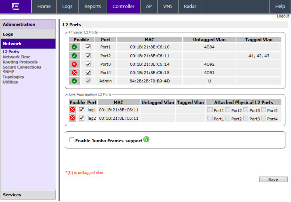
The L2 Ports
tab presents the Physical (that is, Ethernet) and LAG (Link Aggregation Group) (peer to peer) data ports that exist on the controller. These
ports cannot be deleted and new ones cannot be created.
LAG ports
are statically configured by adding/removing physical ports from the LAG.
Physical port belong to at most one LAG at one time. L2 port attached to a
LAG port does not have any properties and could not be attached to any
topology. The L2 ports attached to LAG ports can be enabled or disabled.
Optional, if changes occur to the port physical parameters (speed, half or
full duplex), a warning will be displayed to indicate that the L2 port does
not meet LAG conditions.
Considerations for attaching/detaching regular L2 ports to LAG ports:
- Regular L2 port should not have any bridged and
physical topologies associated with the port.
- Regular L2 port should not be disabled.
- L2 ports can be detached from LAG ports regardless
of any topologies attached to the LAG port.
- If the L2 port is the last remaining in LAG, a
warning will be issued. If last port of the LAG has been detached, the
LAG should be in operational DOWN state.
- After detaching the L2 port, it could be attached to
any bridged or physical topology or points via a routing table to the
port any Routed topology.
- Jumbo Frames support is a feature that allows the
configuration of physical Maximum Transmission Unit (MTU) sizes larger
than the standard 1500 bytes on the AP and controller. When Jumbo Frames
is enabled, the maximum MTU is 1800 bytes.
-
Assigning any bridged or physical topology without specifying an L2 port is not
supported. However, you can move any bridged and physical topology to either a
physical or LAG L2 port.
Physical:
- C5110 — Three data ports, displayed as esa0, esa1,
and esa2.
- C5210 — Four data ports, displayed as esa0, esa1,
esa2, and esa3.
- C4110 — Four data ports, displayed as Port1, Port2,
Port3, and Port4.
- C25 — Two data ports, displayed as esa0 and
esa1.
- C35 — Four data ports, displayed as esa0, esa1,
esa2, and esa3.
- V2110 — Two data ports, displayed as esa0 and
esa1.
Link
Aggregation:
- C5110
— One data port, displayed as lag1
- C5210
— Two data ports, displayed as lag1 and lag2.
- C4110
— Two data ports, displayed as lag1 and lag2.
- C35 — Two data ports, displayed as lag1
and lag2.
- C25 — One data port, displayed as lag1.
-
An “Admin” port is created by default. This represents a physical port,
separate from the other data ports, being used for management connectivity. For
more information, see Configuring the Admin Port.
Parameters displayed for the L2
Ports are:
- Operational status,
represented graphically with a green checkmark (UP) or red X (DOWN).
This is the only configurable parameter.
- Port name, as described
above.
- MAC address, as per
Ethernet standard.
- Untagged VLAN (Virtual LAN), displays the associated untagged VLAN ID. This ID
is unique among topologies.
- Tagged VLAN, displays the
associated tagged VLAN ID.
- Attached Physical L2 Ports (Link Aggregation L2
Ports only) select the physical L2 ports associated with the link
aggregation L2 Ports.
- If desired, change the operational status by clicking the Enable checkbox.
You can change the operational state for each port. By
default, data interface states are enabled. If they are not enabled, you can
enable them individually. A disabled interface does not allow data to flow
(receive/transmit).
- If support of MTU sizes above 1500 bytes
is required, click Enable Jumbo Frames support.
This will extend the MTU size to 1800 bytes on the data link layer.
Enabling Jumbo Frames support requires that port speed to
be 1Gbps or higher on the controller and the APs which support Jumbo Frames.
Jumbo Frames are not supported on 10 or 100 Mbps speeds.

 Print
this page
Print
this page Email this topic
 Feedback
 View PDF
 Download EPUB