Viewing and Changing
the Physical Topologies
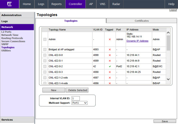
To View and Change the L2 Port Topologies:
-
From the top menu, click
Controller.
-
In the left pane, click . The Topologies tab is displayed.
An associated topology entry is created by default for each L2 Port with the same name.
-
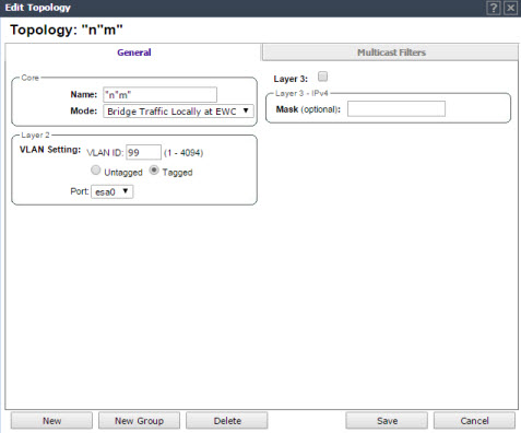
To change any of the
associated parameters, click on the topology entry to be modified. The Edit
Topology dialog appears.
For the data
ports predefined in the system, Name and Mode are not configurable.
-
Optionally, configure one of the physical topologies for Third Party AP connectivity by clicking the 3rd Party AP Topology checkbox.
You must configure a topology to which you will be connecting third-party APs by checking this box. Only one topology can be configured for third-party APs.
Third-party APs must be deployed within a segregated network for which the controller becomes the single point of access (i.e., routing gateway). When you define a third-party AP topology, the interface segregates the third-party AP from the remaining network.
-
To configure an interface
for VLAN (Virtual LAN) assignment, configure the VLAN Settings in the Layer 2
box.
When you
configure a controller port to be a member of a VLAN, you must ensure that the
VLAN configuration (VLAN ID, tagged or untagged attribute, and Port ID) is matched
with the correct configuration on the network switch.
-
To replicate topology settings, click Synchronize in the Status box.
-
If the desired IP configuration is different from the one displayed, change the Interface IP and Mask accordingly in the Layer 3 box.
For this type of data interface, the Layer 3 check box is selected automatically. This allows for IP Interface and subnet configuration together with other networking services.
-
The MTU value specifies the Maximum Transmission Unit or maximum packet size for this topology. The fixed value is 1500 bytes for physical topologies.
If you are using
OSPF (Open Shortest Path First), be sure that the MTU of all the interfaces
in the OSPF link match.

Note
If the
routed connection to an AP traverses a link that imposes a lower MTU than the
default 1500 bytes, the controller and AP participate in automatic MTU discovery
and adjust their settings accordingly. At the controller, MTU adjustments are
tracked on a per AP basis. If the
ExtremeWireless
software cannot discover the MTU size, it enforces the
static MTU size.
-
To enable AP registration through this interface, select the AP Registration checkbox.
Wireless APs use this port for
discovery and registration. Other controllers can use this port to enable
inter-controller device mobility if this port is configured to use SLP or the
controller is running as a manager and SLP is the discovery protocol used by the
agents.
-
To enable management
traffic, select the Management Traffic checkbox.
Enabling management provides access to SNMP (Simple Network Management Protocol) (v1/v2c,
v3), SSH, and HTTPs management interfaces.
Note
This option does not override the built-in protection
filters on the port. The built-in protection filters for the port, which are
restrictive in the types of packets that are allowed to reach the management
plane, are extended with a set of definitions that allow for access to system
management services through that interface (SSH, SNMP, HTTPS:5825).
-
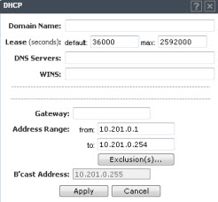
To enable the local
DHCP (Dynamic Host Configuration Protocol) Server on the controller, in the DHCP box, select Local
Server. Then, click on the Configure
button to open the DHCP
configuration pop up window.
Note
The local DHCP Server is useful as a general-purpose DHCP
Server for small subnets.
-
In the Domain Name box, type the
name of the domain that you want the APs to use for DNS Server‘s
discovery.
-
In the Lease (seconds) default box,
type the time period for which the IP address will be allocated to the APs (or
any other device requesting it).
-
In the Lease (seconds) max box, type
the maximum time period in seconds for which the IP address will be allocated
to the APs.
-
In the DNS Servers box, type the DNS
Server‘s IP address if you have a DNS Server.
-
In the WINS box, type the WINS
Server‘s IP address if you have a WINS Server.
Note
You can type multiple entries in the
DNS Servers and
WINS boxes. Each entry
must be separate by a comma. These two fields are not mandatory to enable
the local DHCP feature.
-
In the Gateway box, type the IP
address of the default gateway.
Note
Since the controller is not allowed to be the gateway
for the segment, including APs, you cannot use the Interface IP address as
the gateway address for physical and Bridged at Controller topology. For
Routed topology, the controller IP address must be the gateway.
-
Configure the address range from which the local DHCP Server will allocate IP
addresses to the APs.
- In
the Address Range: from
box, type the starting IP address of the IP address
range.
- In
the Address Range: to box,
type the ending IP address of the IP address range.
-
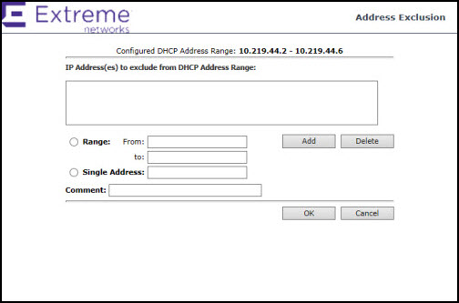
Click the Exclusion(s) button to
exclude IP addresses from allocation by the DHCP Server. The DHCP Address
Exclusion window opens.
The controller
automatically adds the IP addresses of the Interfaces (Ports), and the default
gateway to the exclusion list. You cannot remove these IP addresses from the
exclusion list.
- Select Range. In the From box, type the starting IP
address of the IP address range that you want to exclude from the DHCP
allocation.
- In the To
box, type the ending IP address of the IP address range that you want to exclude
from the DHCP allocation.
- To exclude a single address, select the Single
Address radio button and type the IP address in the adjacent box.
- In the Comment box, type any relevant comment. For example, you can type
the reason for which a certain IP address is excluded from the DHCP
allocation.
- Click Add.
The excluded IP addresses are displayed in the IP Address(es) to
exclude from DHCP Address Range box.
- To delete a IP Address from the exclusion list,
select it in the IP Address(es) to exclude from DHCP
Range box, and then click Delete.
- To save your changes, click OK.
-
Click Close to close
the DHCP
configuration window.
Note
The Broadcast (B‘cast) Address field is view only.
This field is computed from the mask and the IP addresses.
-
You are returned to the L2 port topology edit window.
 Print
this page
Print
this page Email this topic
 Feedback
 View PDF
 Download EPUB