Connecting Redundant Power Cables for the EPS-C2 Chassis

The EPS-C2 chassis can use up to five 2x7-pin redundant power connectors, shown in EPS-C2 2x7 Pin Redundant Power Cable with Connector Key Tab, which connect the power supply to ExtremeSwitching X440-G2 and X620 switches.
Click to expand in new window
EPS-C2 2x7 Pin Redundant Power Cable with Connector Key Tab

The redundant power cable has keyed ends. The key is a plastic tab on the cable connector housing to ensure correct alignment of the connector. The keyed ends of the 2x7 cable are not symmetrical; one end of the cable will fit into the EPS-C2 chassis and the other end will fit into the switch.

After the EPS-C2 has been installed in a rack and the power supplies have been installed, do the following to connect the redundant power cables:

  1. Set the connector selection switch, located on the front of the EPS-C2 chassis, for the 2x7 connector.
    See EPS-C2 Connector Selector Switch.
    Click to expand in new window
    EPS-C2 Connector Selector Switch
  2. Connect the keyed end (for the 2x7 connector cable, the end with the tab offset from the edge of the connector pins) of the redundant power cord to the EPS-C2 chassis.
  3. Verify that the side of the connector marked TOP is facing up.
  4. Connect the other end of the redundant power cable (for the 2x7 connector cable, the end with the key flush with the edge of the connector pins) to the switch.
    See Installing the Redundant Power Cord.

    Be sure that the side of the connector marked TOP is facing up.

    Click to expand in new window
    Installing the Redundant Power Cord
    Note

    Note

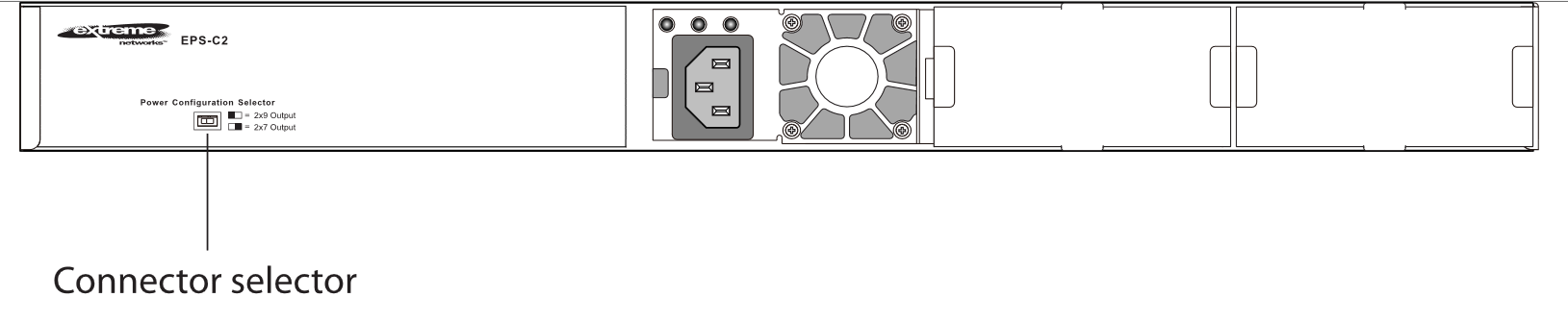
    The EPS-C2 2x9 connector, shown in the figure to the left of where the cable is connected, is used only with older switch models that are not compatible with ExtremeXOS version 21.1 and later.
  5. Repeat the preceding steps to connect any additional redundant power cords.