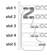
The figure is intended to show cable connections between switches. Details of the
switches themselves, such as the location of the stacking ports and fan modules, might
differ from those of the switches that actually would be used.
The following cables are used to make the stacking connections:
QSFP+ cable connecting the two switches at the top (slot 1
and slot 2)
SFP+ cable connecting the switch in slot 2 with the switch
in slot 3
SFP+ cable connecting the switch in slot 3 with the switch
in slot 4
SFP+ cable connecting the switch in slot 4 with the switch
in slot 5
SFP+ cable connecting the switch in slot 5 with the switch
in slot 1