ExtremeXOS software supports:
By default, DMM is not enabled. You must explicitly enable the DMM transmission for a CFM segment, either as continuous or on-demand mode.
A network interface is considered attached to a subnetwork. The term segmentis used to refer to such a subnetwork, whether it be an Ethernet LAN, a ring, a WAN link, or even an SDH virtual circuit.
Frame-Delay measurement is done between two specific end points within an administrative domain. Frame delay and frame delay variation measurements are performed in a maintenance association end point (MEP) by sending and receiving periodic frames with ETH-DM information to and from the peer end point during the diagnostic interval.
When a CFM segment is enabled to generate frames with ETH-DM information, it periodically sends frames with ETH-DM information to its peer in the same maintenance association (MA) and expects to receive frames with ETH-DM information from its peer in the same MA.
A node transmits frames with ETH-DM information with the following information element:
Whenever a valid DMM frame is received by the peer, a DMR frame is generated and transmitted to the requesting node.
The switch makes two-way frame delay variation measurements based on its ability to calculate the difference between two subsequent two-way frame delay measurements.
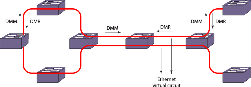
The PDUs used to measure frame delay and frame delay variation are the DMM and the DMR PDUs where DMM is initiated from a node as a request to its peer and DMR is the reply from the peer.
If you try to enable the transmission for a CFM segment whose configuration is not complete, the trigger is rejected and an error message similar to the following is given:
ERROR: CFM Configuration is not complete for segment "s1" to start transmission

Note
A CFM segment without a domain and an association is considered to be an incomplete segment.Upon enabling the transmission from a CFM segment, the segment transmits DMM frames, one at each transmit-interval which is configured through the CLI. If the user enables on-demand transmission, the segment transmits "X" number of DMMs and moves back to the disabled state, where "X" is the number of frames specified by the user through the CLI.
For continuous transmission, the segment continues to transmit DMM frames until stopped by the user. This transmission continues even after reboot for both continuous and on-demand mode. For on-demand transmission, the segment, which was enabled to transmit "X" number of frames, and is still transmitting, starts transmitting again "X" number of frames after reboot, or failover, or process restart. The old statistics are not preserved for both continuous and on-demand mode for all the above three scenarios.
Upon transmitting a DMM, the segment is expected to get a reply from the destination within the specified time. If a reply is received after that time, that reply will be considered as a delayed one.
If a reply is not received within the transmit-interval, that is, between two subsequent DMM transmissions, then that frame is considered as lost. Once the percentage of the sum of lost and delayed frames reaches the alarm threshold, an alarm is generated and the segment is moved to the alarming state. This state is maintained until the percentage of valid replies reaches the clear threshold. These alarm and clear states are maintained for a specified window, which holds a set of recent frames and their corresponding delays.
The mean delay and delay variance for the current window is also measured whenever the user polls the segment statistics.
 Print
this page
Print
this page Email this topic
 Feedback
 View PDF
 Download EPUB