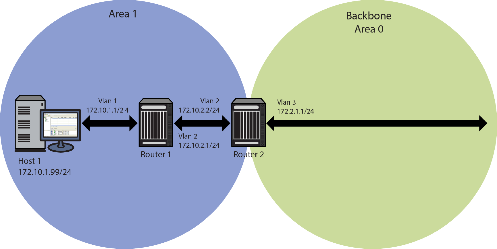
Basic OSPF Topology provides an overview of a basic OSPF topology. This topology displays two areas: a backbone area which must exist in any OSPF topology and a directly connected area 1. See Configuring OSPF Areas for a full discussion of OSPF area configuration. This basic configuration requires the configuration of three interfaces and associated IP addresses, three networks, and two routers on a single OSPF router instance.
The following example configures the basic OSPF topology as displayed in Basic OSPF Topology:
Router 1(rw)->configure
Router 1(rw-config)->interface vlan 1
Router 1(rw-config-intf-vlan.0.1)->ip address 172.10.1.1 255.255.255.0
Router 1(rw-config-intf-vlan.0.1)->exit
Router 1(rw-config)->interface vlan 2
Router 1(rw-config-intf-vlan.0.2)->ip address 172.10.2.1 255.255.255.0
Router 1(rw-config-intf-vlan.0.2)->exit
Router 1(rw-config)->router ospf 1
Router 1(rw-config-ospf-1)->network 172.10.1.0 0.0.0.255 area 1
Router 1(rw-config-ospf-1)->network 172.10.2.0 0.0.0.255 area 1
Router 1(rw-config-ospf-1)->exit
Router 1(rw-config)->
Router 2(rw)->configure
Router 2(rw-config)->interface vlan 2
Router 2(rw-config-intf-vlan.0.1)->ip address 172.10.2.2 255.255.255.0
Router 2(rw-config-intf-vlan.0.1)->exit
Router 2(rw-config)->interface vlan 3
Router 2(rw-config-intf-vlan.0.2)->ip address 172.2.1.1 255.255.255.0
Router 2(rw-config-intf-vlan.0.2)->exit
Router 2(rw-config)->router ospf 1
Router 2(rw-config-ospf-1)->network 172.10.2.0 0.0.0.255 area 1
Router 2(rw-config-ospf-1)->network 172.2.1.0 0.0.0.255 area 0
Router 2(rw-config-ospf-1)->exit
Router 2(rw-config)->
 Print
this page
Print
this page Email this topic
 Feedback
 View PDF
 Download EPUB