The backbone area 0 cannot be disconnected from any other areas in the AS. Disconnected areas will become unreachable. To establish and maintain backbone connectivity, virtual-links can be configured through non-backbone areas for the purpose of connecting a disconnected area with the backbone through a backbone connected area. The two endpoints of a virtual link are ABRs, both of which belong to the backbone connected area (also referred to as the transit area); one of which belongs to the area disconnected from the backbone. Virtual links cannot be configured through stub areas (see Configuring a Stub Area for stub area configuration information).
The virtual-link is treated as if it were an unnumbered point-to-point network belonging to the backbone and joining the two ABRs. The cost of a virtual link is not configured. It is auto configured with the cost of the intra-area path between the two ABRs that make up the virtual-link.
Use the area virtual-link command in OSPF router configuration command mode, providing the transit area ID and the ABRs IP address, to configure an area virtual-link.
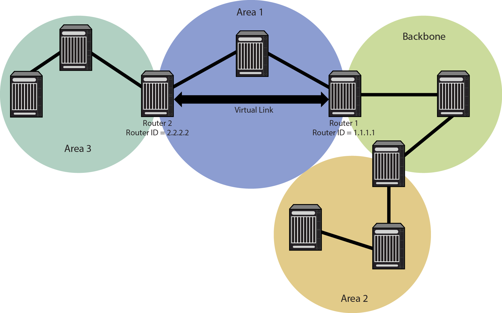
Virtual Link Topology displays a typical virtual-link topology. Area 3 does not share an ABR with the backbone area, and is therefore disconnected from the backbone. Area 3 shares an ABR (router 2) with area 1. Area 1 has a second ABR (router 1) that it shares with the backbone. Area 1 is the transit area because it contains an ABR that it shares with the disconnected area and a second ABR that it shares with the backbone. By configuring an area virtual-link between router 2 and router 1, Area 3 will gain connectivity with the backbone and be able to learn routes for this AS.
The following example presents the configuration required to configure the virtual-link displayed in Virtual Link Topology:
Router 1(rw-config)->router ospf 1
Router 1(rw-config-ospf-1)->area 0.0.0.1 virtual-link 2.2.2.2
Router 1(rw-config-ospf-1)->exit
Router 1(rw-config)->
Router 2(rw-config)->router ospf 2
Router 2(rw-config-ospf-2)->area 0.0.0.1 virtual-link 1.1.1.1
Router 2(rw-config-ospf-2)->exit
Router 2(rw-config)->
An area virtual-link can be configured for either simple or MD5 authentication.
Use the area virtual-link authentication-key command in OSPF router configuration command mode to configure simple authentication on this area virtual-link.
Use the area virtual-link message-digest-key command in OSPF router configuration command mode to configure MD5 authentication on this area virtual-link.
The following timers can be configured for an area virtual-link:
See Configuring OSPF Timers for an OSPF timers discussion.

Note
RFC 2328 specifies that the retransmit-interval should be greater than the expected round-trip delay between the two routers. This may be hard to estimate for a virtual link; it is better to err on the side of making it too large. Print
this page
Print
this page Email this topic
 Feedback
 View PDF
 Download EPUB