The operation of an 802.1Q VLAN switch is best understood from a point of view of the switch itself. To illustrate this concept, the examples that follow view the switch operations from inside the switch.
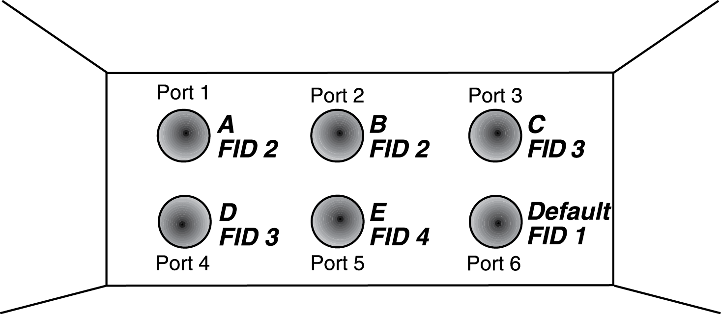
The figure below depicts the inside of a switch with six ports, numbered 1 through 6. The switch has been configured to associate VLAN A and B with FID 2, VLAN C and D with FID 3, and VLAN E with FID 4. It shows how a forwarding decision is made by comparing a frame‘s destination MAC to the FID to which it is classified.
Assume a unicast untagged frame is received on Port 3 in the example in the above figure. The frame is classified for VLAN C (the frame‘s PVID is VLAN C). The switch would make its forwarding decision by comparing the destination MAC address to information previously learned and entered into its filtering database. In this case, the MAC address is looked up in the FDB for FID 3, which is associated with VLANs C and D. Let‘s say the switch recognizes the destination MAC of the frame as being located out Port 4.
Having made the forwarding decision based on entries in the FID, the switch now examines the port VLAN egress list of Port 4 to determine if it is allowed to transmit frames belonging to VLAN C. If so, the frame is transmitted out Port 4. If Port 4 has not been configured to transmit frames belonging to VLAN C, the frame is discarded.
If, on the other hand, a unicast untagged frame is received on Port 5, it would be classified for VLAN E. Port 5 has is own filtering database and is not aware of what addressing information has been learned by other VLANs. Port 5 looks up the destination MAC address in its FID. If it finds a match, it forwards the frame out the appropriate port, if and only if, that port is allowed to transmit frames for VLAN E. If a match is not found, the frame is flooded out all ports that are allowed to transmit VLAN E frames.
 Print
this page
Print
this page Email this topic
 Feedback
 View PDF
 Download EPUB