Virtual Switch Bonding (VSB) is an S- and K-Series feature that allows for the aggregation of links on two physical chassis, providing redundancy, while at the same time allowing ports on both chassis to pass data concurrently, effectively doubling the available bandwidth. VSB aggregates two like chassis into a single virtual network device. VSB joins two chassis into a single system by extending each chassis‘ distribution to the other chassis using one or more 10 or 40GbE uplink ports as bonding interconnect links, depending upon your platform.
The following VSB chassis restrictions apply to VSB system interconnect ports on the K-Series platform:
On the S-Series platform there are two types of VSB interconnect ports depending upon the module and option cards installed:
On the S-Series platform, the following VSB chassis restrictions only apply to VSB systems using standard software assisted Ethernet data interconnect ports, and do not apply to a VSB system using VSB hardware interconnect ports:
Some S-Series modules have dedicated hardware VSB interconnect ports that are either fixed or have the ability to install an option module that contains hardware VSB interconnect ports. These dedicated hardware VSB interconnect ports are not compatible with standard software assisted Ethernet data interconnect ports. An interconnect bonding mode specifies whether the system interconnection is hardware or software based. For both the S-Series and K-Series platforms, each physical chassis in the VSB system must be of the same chassis type, which implies the same number of slots. For example, two S4 chassis become a single system with 8 slots; two SSAs become a single system with 2 slots. The interconnect ports connecting the physical chassis are designated as bonding ports on each chassis and create the virtual backplane that ties the two physical chassis together.
The Link Failure Response (LFR) protocol provides for the configuration of one or more monitor links. In the unlikely event that all interconnect links should go down or otherwise fail, the LFR monitor link determines whether both chassis are still operational and places the chassis with the lowest LFR priority in a dormant state until at least one interconnect link is restored. These links do not carry user traffic. The sole purpose of a an LFR link is to resolve which physical chassis should remain operational when all bonding ports are non-functional.
If VSB hardware ports are present on the S-Series device, in order to use the VSB hardware ports, VSB bonding mode must be set to hard, and the hardware port must be enabled using its vsb.x.y name for the hardware ports to be used as VSB bond ports. When in VSB hardware bonding mode, any 10GbE or 1GbE ports enabled for VSB are LFR ports. If VSB bonding mode is set to soft, any VSB hardware ports present will not function. Any 10GbE software ports enabled for VSB are used as VSB bond ports. Any 1GbE software ports enabled for VSB are LFR ports.
On S-Series devices that do not contain VSB hardware ports, VSB bonding mode must be set to the default value of soft. 10GbE software ports enabled for VSB are used as VSB bond ports. All 1GbE software ports enabled for VSB are LFR ports.
On the K-Series, VSB bond ports are supported on fabric module 10GbE ports enabled for VSB. 1 and 10GbE ports enabled for VSB on non-fabric modules are LFR ports.
VSB is typically used in a data center between two switches, of the same type, LAGed to a server on one side and to network devices on the other.
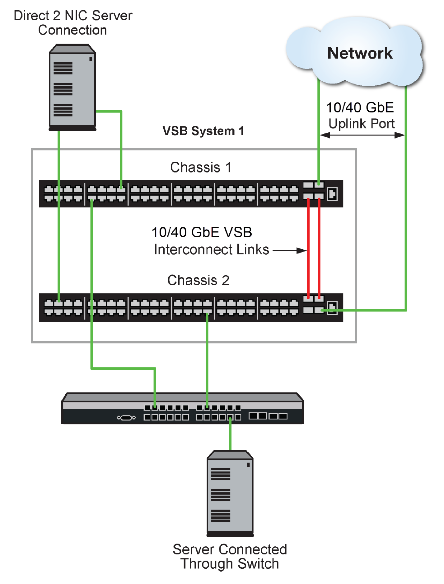
VSB Data center Configuration Overview presents an overview of a two SSA chassis VSB system in a data center context. The upper chassis is configured as VSB chassis 1. The lower chassis is configured as VSB chassis 2. These chassis are members of VSB system 1. On each chassis, uplink ports are used to create the interconnect links that aggregate the two chassis into a single virtual network device. Non-VSB 10GbE ports provide the uplink connections to the network.
In VSB Data center Configuration Overview, a server with two NICs installed achieves redundancy through a direct connection, distributing the two NIC connections between the two available VSB system slots. A single NIC server achieves redundancy through an intermediate switch that distributes multiple connections between the two VSB system slots.
A VSB system is managed by a single IP address and behaves as if it is one chassis with double the slots. Once globally enabled, VSB system IP address configuration is the same as for a non-VSB system.
The VSB system provides gains in network resiliency, performance, and management through:
Though bandwidth and port capacities scale in a VSB system, feature capacities such as route, MAC address tables and user capacities remain the same as in a single chassis system.
On the S-Series, VSB licensing is required per chassis unless the chassis contains at least one module that is automatically entitled to VSB. See the release notes that come with the firmware for module VSB entitlement details.
Using the High Availability feature, slots can be grouped such that forwarding is maintained while individual slot groups are firmware upgraded, so long as a group that is not being upgraded continues to provide the interconnect between VSB chassis.
A non-default MAC address can be manually set prior to globally enabling the VSB system.
An outport local preference can be configured for the local chassis, setting a likelihood that a packet will egress the system using a LAG port on the local chassis and not utilize the VSB interconnect link.
A preference for local chassis LAG ports can be set to none, weak, strong or forced.
 Print
this page
Print
this page Email this topic
 Feedback
 View PDF
 Download EPUB