Virtual Switch Bonding (VSB) stacking is an Extreme Networks 7100-Series feature that allows for the aggregation of links on up to 8 physical chassis, providing redundancy, while at the same time allowing ports on all chassis to pass data concurrently. VSB aggregates multiple chassis into a single virtual network device. VSB joins multiple chassis into a single system by extending each chassis‘ distribution to the next chassis in the stack using one or more 40GbE port interconnect links. Any mix of 7100-Series family units – 7100G and 7100K can be VSB stacked.
The 40GbE ports connecting the physical chassis are designated as bonding ports on each chassis and create the virtual backplane that ties the two physical chassis together.
VSB stacking supports the Link Failure Response (LFR) feature. LFR is a mechanism designed to protect against what is often referred to as the “split brain” problem using LFR priority configuration as a means of determining which surviving stack segment will remain up when a link or chassis failure occurs. This problem occurs when a VSB stack splits into two or more segments, due to the failure of a bonding link or individual chassis, resulting in duplication of managements network interfaces. This scenario can result in serious disruptions to the customer network.
40GbE VSB stacking configured ports are always set as interconnect ports. 1 or 10 GbE VSB configured ports are always set as LFR monitor ports.

Note
A closed ring configuration configures an interconnect link between the first and last 7100-Series chassis in the stack. Closed ring configurations are not required, but are highly recommended. A system or interconnect link failure in an open loop configuration can result in separate bonded systems both using the same IP address. When a system or interconnect link failure occurs in a closed ring configuration, this issue will not occur.VSB is typically used in a data center between switches LAGed to a server on one side and to network devices on the other.
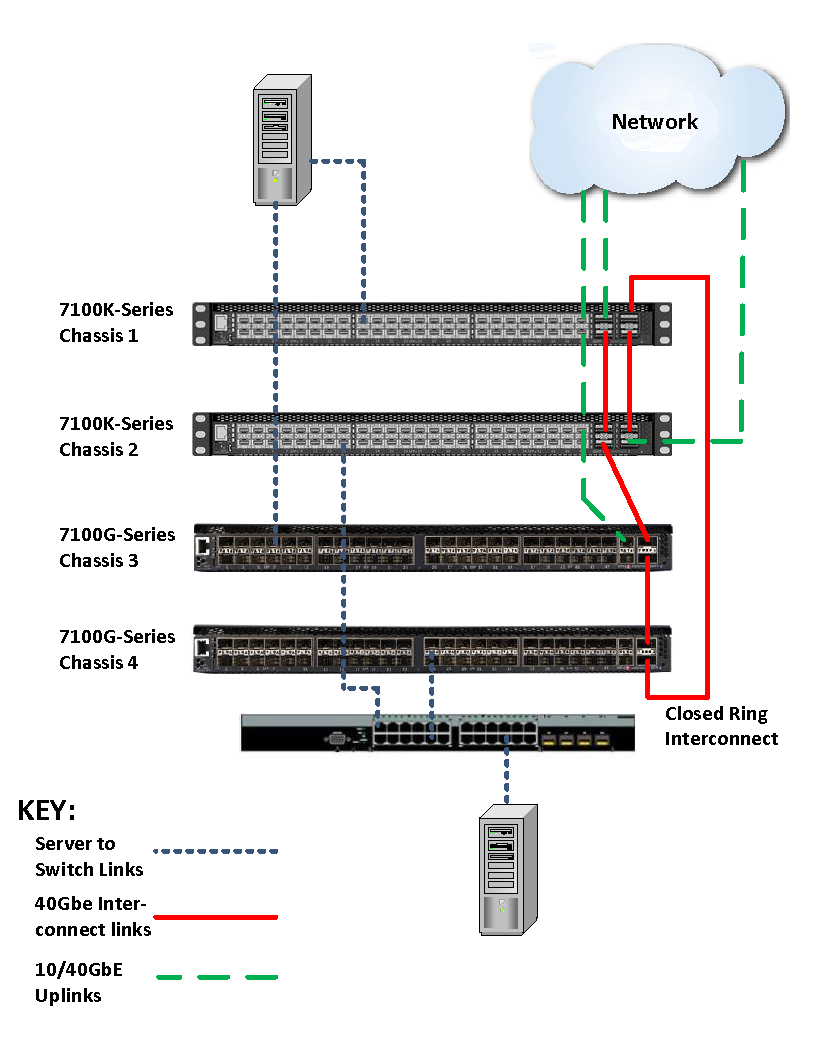
VSB Stacking Data center Configuration Overview presents an overview of a four chassis VSB stacking system in a data center context. The top two 7100K-Series chassis (Chassis 1 and 2) have four 40GbE links, two of which are used as redundant VSB stacking interconnect links. Chassis are configured in order from top to bottom as VSB chassis 1, 2, 3, and 4. These chassis are members of VSB system 1. Between chassis 1 and 2, two 40GbE interconnect links are used providing a redundant interconnect link. Chassis 1 uses a third 40GbE port to provide a closed ring configuration between chassis 1 and 4. There is a single VSB interconnect link between chassis 2-to-3, 3-to-4, and 4-to-1. The fourth 40GbE port on chassis 1 and 2 are used as uplinks to the network. 10GbE ports on chassis 3 and 4 can also be used uplink ports to the network.
In VSB Stacking Data center Configuration Overview, a server with two NICs installed achieves redundancy through a direct connection, distributing the two NIC connections between the two available VSB system slots. A single NIC server achieves redundancy through an intermediate switch that distributes multiple connections between the two VSB system slots.
Assuming fg.x.1 of each chassis is connected to fg.x.2 of the next chassis, with fg.4.1 creating a closed ring by interconnecting to fg.1.2, the show bonding display for VSB Stacking Data center Configuration Overview would be:
System(rw)->show bonding
Global Bonding State    : enabled
Max Bonded Chassis      : 8
Max Bonded System Slot  : 8
Slots active in System  : 1-8
Bonding Admin System MAC: 00-00-71-00-00-71
Bonding Oper System MAC : 00-00-71-00-00-71
Link Failure Response   : disabled
          System                              Shared   LFR      Active Slot IDs
Chassis Identifier  Serial Number  Status     Secret Priority  For This Chassis
------- ---------- --------------- ---------- ------ -------- -----------------
   1           999 TOR000035       up             no       10                 1
   2           999 124700016845    up             no       20                 2
   3           999 13190048685E    up             no       30                 3
   4           999 13170490685E    up             no       40                 4
Port          Admin    Partner       Oper     Oper
              Status   Port          Mode     Status
------------- -------- ------------- -------- ----------------
fg.1.1        enabled  fg.2.2        bonding  up
fg.1.2        enabled  fg.4.1        bonding  up
fg.2.1        enabled  fg.3.2        bonding  up
fg.2.2        enabled  fg.1.1        bonding  up
fg.3.1        enabled  fg.4.2        bonding  up
fg.3.2        enabled  fg.2.1        bonding  up
fg.4.1        enabled  fg.1.2        bonding  up
System(rw)->
Note
A closed ring interconnect is not required, but if you do not close the ring and an interconnect or a system failure occurs, the remaining systems could be divided, causing two systems to reside in your network with the same IP address.A VSB stacking system is managed by a single IP address and behaves as if it is one chassis with multiple slots. Once globally enabled, VSB system IP address configuration is the same as for a non-VSB multi-slot system.
The VSB stacking system provides gains in network resiliency, performance, and management through:
Though bandwidth and port capacities scale in a VSB system, feature capacities such as route, MAC address tables and user capacities remain the same as in a single chassis system.
When activating an advanced routing license on a 7100-Series VSB stacking system, you must activate the license on all chassis in the system.
Using the High Availability feature, slots can be grouped such that forwarding is maintained while individual slot groups are firmware upgraded, so long as a group that is not being upgraded continues to provide the interconnect between VSB chassis.
A non-default MAC address can be manually set prior to globally enabling the VSB system. VSB stacking chassis can be configured with unique MAC addresses or the same MAC address. It is recommended that you configure all chassis in the VSB system with the same MAC address.
 Print
this page
Print
this page Email this topic
 Feedback
 View PDF
 Download EPUB