This example provides a link aggregation configuration example that includes an edge switch, a distribution switch, and two Fixed Switches that will aggregate both end-users at the edge and the data from a local server.
See Example 1 Multiple Device Configuration for an illustration of this example, including port, key, and system priority assignments.
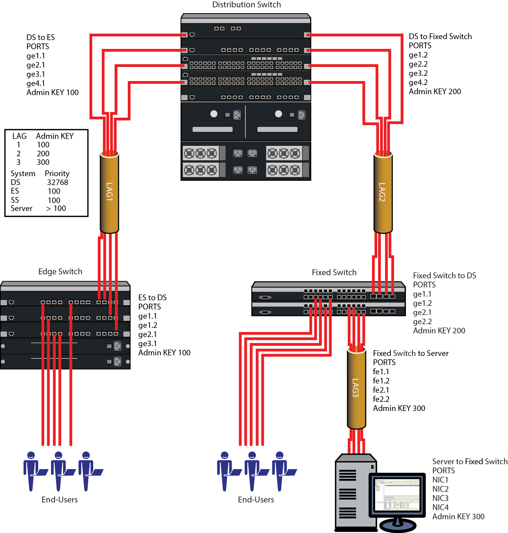
Three LAGs are created for the example:
Each LAG consists of four ports. The primary goal of the aggregates in this example is to provide link and slot redundancy for the affected data streams. With that in mind, LAG members are spread between available system slots. Four out of the five distribution switch available slots are used providing complete redundancy at the distribution switch. All three slots are used in the edge switch. The four ports from the server to the Fixed Switches and the Fixed Switches to the distribution switch are evenly split between the two Fixed Switches.
For this example we will manually configure the LAGs that will form and prevent any other LAGs from forming. Because we have specific port to LAG goals in mind, the first thing we want to do on each device is to ensure that LAGs form only where we configure them. Since the admin key for the LAG and its associated ports must agree for the LAG to form, an easy way to ensure that LAGs do not automatically form is to set the admin key for all LAGS on all devices to a non-default value. The physical ports will initially retain admin key defaults. In our example, the admin keys for all LAGs are set to the highest configurable value of 65535.
Both physical port and LAG admin keys will be set as shown in the following table to ensure that the LAGs form only for the desired ports.
LAG and Physical Port Admin Key Assignments
| Device | LAG | LAG Admin Key | Physical Port | Physical Port Admin Key |
|---|---|---|---|---|
| Distribution Switch | 1 | 100 | ge.1.1 | 100 |
| ge.2.1 | 100 | |||
| ge.3.1 | 100 | |||
| ge.4.1 | 100 | |||
| 2 | 200 | ge.1.2 | 200 | |
| ge.2.2 | 200 | |||
| ge.3.2 | 200 | |||
| ge.4.2 | 200 | |||
| Edge Switch | 1 | 100 | ge.1.1 | 100 |
| ge.1.2 | 100 | |||
| ge.2.1 | 100 | |||
| ge.3.1 | 100 | |||
| Fixed Switch | 2 | 200 | ge.1.1 | 200 |
| ge.1.2 | 200 | |||
| ge.2.1 | 200 | |||
| ge.2.2 | 200 | |||
| 3 | 300 | ge.1.1 | 300 | |
| ge.1.2 | 300 | |||
| ge.2.1 | 300 | |||
| ge.2.2 | 300 | |||
| Server | 3 | 300 | NIC1 ETH | 300 |
| NIC2 ETH | 300 | |||
| NIC3 ETH | 300 | |||
| NIC4 ETH | 300 |
Which device determines port selection for the LAG is an optional consideration. If system priorities remain at the default value, the lowest MAC address device determines port selection for the LAG. For purposes of this example, we will set the system priority of the edge switch to 100 to ensure it will control port selection for LAG1, instead of the distribution switch. The Fixed Switch system priority will be set to 100 to ensure it will control port selection for LAG2, instead of the distribution switch. For the Fixed Switch to control port selection for LAG3 requires that you ensure that the server has a system priority higher than 100.
Each LAG in our example is made up of physical ports of the same speed, so there is no need to set the port priority to a non-default value. The only port value to be changed is the admin key for each physical port and each LAG. These modifications are detailed in LAG and Physical Port Admin Key Assignments.
Given that the intent of the example is to have three LAGs of 4 ports each, there is no need to enable the single port LAG feature. Once the LAGs initiate, they will persist across resets. Should only a single port be active after a reset, the LAG will form regardless of the single port LAG feature setting.
Flow regeneration (S-, K-Series) is enabled for the distribution switch and edge switch in our example. This setting will ensure that should a LAG port become disabled and then become active again, LACP will redistribute existing flows over all the ports in the new LAG. Both the 7100-Series and Fixed Switch platforms do not support flow regeneration.
The output algorithm defaults to selecting the output port based upon the destination and source IP address. This setting will not be changed in our example. In any case, note that the Fixed Switch does not support the output algorithm feature.
 Print
this page
Print
this page Email this topic
 Feedback
 View PDF
 Download EPUB