DVMRP routing is implemented on Extreme Networks devices as specified in RFC 1075 and draft-ietf-idmr-dvmrp-v3-10.txt.
Extreme Networks devices support the following DVMRP components:
Each DVMRP-enabled interface transmits multicast probe packets to inform other DVMRP routers that it is operational. Probe messages are sent every 10 seconds on every interface running DVMRP. These messages provide:
Each DVMRP-enabled device builds a DVMRP route table to maintain routes to all networks involved in DVMRP routing. As shown in the following example, the DVMRP route table contains a destination and next hop IP address, associated interface, metric value, expiration time, and up-time.
System(su)->show ip dvmrp route
Destination        Next Hop        Interface    Metric  Expire   Uptime
----------------------------------------------------------------------------
9.9.9.0/24         168.3.2.1       vlan.0.3200  3       00:01:52 2d, 19:34:45
21.2.2.0/24        168.3.2.1       vlan.0.3200  2       00:01:52 3d, 01:14:49
21.21.21.0/24      168.3.2.1       vlan.0.3200  2       00:01:52 3d, 01:14:49
29.2.2.0/24        168.3.2.1       vlan.0.3200  2       00:01:52 3d, 01:14:49
32.1.1.0/24        168.3.2.1       vlan.0.3200  2       00:01:52 3d, 01:14:49
32.11.11.0/24      168.3.2.1       vlan.0.3200  2       00:01:52 3d, 01:14:49
92.9.2.0/24        168.3.2.1       vlan.0.3200  2       00:01:52 3d, 01:14:49
100.3.3.0/24       Connected       vlan.0.3200  1       00:00:00 02:09:22
129.2.9.0/24       168.3.2.1       vlan.0.3200  2       00:01:52 2d, 19:02:06
139.3.9.0/28       Connected       vlan.0.390   1       00:00:00 3d, 01:14:54
160.2.2.0/24       168.3.2.1       vlan.0.3200  2       00:01:52 3d, 01:14:49
168.2.1.0/24       168.3.2.1       vlan.0.3200  2       00:01:52 3d, 01:14:49
168.3.0.0/16       Connected       vlan.0.3200  1       00:00:00 02:09:22
168.3.1.0/26       Connected       vlan.0.3100  5       00:00:00 2d, 21:54:44
168.8.1.0/24       168.3.2.1       vlan.0.3200  3       00:01:52 2d, 19:34:25
188.21.21.0/24     168.3.2.1       vlan.0.3200  2       00:01:52 3d, 01:14:49
188.23.23.0/24     168.3.2.1       vlan.0.3200  2       00:02:02 3d, 01:14:49
189.8.9.0/24       168.3.2.1       vlan.0.3200  4       00:02:02 2d, 19:34:15
191.9.1.0/24       168.3.2.1       vlan.0.3200  3       00:02:02 2d, 19:34:45
191.9.9.0/24       168.3.2.1       vlan.0.3200  3       00:02:02 2d, 19:34:45
192.9.2.0/24       168.3.2.1       vlan.0.3200  2       00:02:02 3d, 01:14:49
193.9.3.0/24       Connected       vlan.0.930   1       00:00:00 3d, 01:14:54
198.9.8.0/24       168.3.2.1       vlan.0.3200  4       00:02:02 2d, 19:34:15
198.23.23.0/24     168.3.2.1       vlan.0.3200  2       00:02:02 3d, 01:14:49
199.23.23.0/24     168.3.2.1       vlan.0.3200  2       00:02:02 3d, 01:14:49
250.9.9.0/24       168.3.2.1       vlan.0.3200  2       00:02:02 3d, 01:14:49
The number of DVMRP routes is  26
DVMRP-enabled devices send route report packets to adjacent DVMRP devices every 60 seconds. When a DVMRP device receives one, it checks to verify that the report is from a known neighbor before processing.
The first time a device sees its own address in a neighbor‘s probe packet, it sends a unicast copy of its entire routing table to the neighbor to reduce start-up time.
The route report packet contains data about all networks/routes of which the sending device is aware. This information is used to determine the reverse path back to a particular multicast source. Every DVMRP device keeps a separate metric associated with each route. This metric is the sum of all interface metrics between the device originating the report and the source network.
DVMRP devices accept route reports for aggregated source networks in accordance with classless inter-domain devices (CIDR). This means that, if a prune or graft is received on a downstream interface for which the source network is aggregated, then a prune or graft should be sent upstream (to the multicast source).
If a DVMRP device has a large number of DVMRP routes, it will spread route reports across the route update interval (60 seconds) to avoid bottlenecks in processing and route synchronization issues.
For the purpose of pruning, DVMRP needs to know which downstream routes depend on the device for receiving multicast streams. Using poison reverse, the upstream router maintains a table of the source network and all downstream devices that are dependent on the upstream device.
DVMRP-enabled devices use the mroute table to maintain a source-specific forwarding tree.
When a DVMRP device is initialized, it assumes the role of the designated forwarder for all of its locally attached networks. Before forwarding any packets, all devices use IGMP to learn which networks would like to receive particular multicast group streams. In the case of a shared network, the device with a lower interface metric (a configurable value), or the lower IP address will become the designated forwarder.
A DVMRP device forwards multicast packets first by determining the upstream interface, and then by building the downstream interface list. If a downstream router has no hosts for a multicast stream, it sends a prune message to the upstream router. If the upstream router‘s outbound list is now empty, it may send a prune message to its upstream router.
If a downstream device has pruned a multicast group that a host would like to now receive, the downstream device must send a DVMRP graft message to its upstream device. The DVMRP graft will traverse the source-specific multicast delivery tree to the device that is receiving this stream.
As shown in the following example, the Mroute table displays the incoming interface IP address, the multicast group address, the uptime of the stream, incoming interface port number, and the outgoing interface port number.
System(su)->show ip mroute
IP Multicast Routing Table
Flags: D - Dense, S - Sparse, C - Connected, L - Local, P - Pruned
       R - RP-bit set, F - Register flag, T - SPT-bit set, J - Join SPT
Timers: Uptime/Expires
  DVMRP (191.9.1.11/32, 234.1.1.1), 00:00:36/00:00:00, flags:
        Incoming interface: vlan.0.3200
        Outgoing interface list:
  DVMRP (191.9.1.12/32, 234.1.1.1), 00:00:36/00:00:00, flags:
        Incoming interface: vlan.0.3200
        Outgoing interface list:
  DVMRP (193.9.3.30/32, 234.3.3.3), 3d, 01:13:10/00:00:00, flags:
        Incoming interface: vlan.0.930
        Outgoing interface list:
          vlan.0.3100, Forward/DVMRP, 2d, 19:32:38/00:00:00
  DVMRP (193.9.3.31/32, 234.3.3.3), 3d, 01:13:04/00:00:00, flags:
        Incoming interface: vlan.0.930
        Outgoing interface list:
          vlan.0.3100, Forward/DVMRP, 2d, 19:32:38/00:00:00
  DVMRP (193.9.3.32/32, 234.3.3.3), 3d, 01:13:11/00:00:00, flags:
        Incoming interface: vlan.0.930
        Outgoing interface list:
          vlan.0.3100, Forward/DVMRP, 2d, 19:32:38/00:00:00
If a device receives a datagram that has no IGMP group members present, and all the downstream networks are leaf networks, the device sends a prune packet upstream to the source tree.
When sending a prune upstream, the device:
This value should be the minimum of the default prune lifetime (randomized to prevent synchronization) and the remaining prune lifetimes of the downstream neighbors.
To ensure the prune is accepted, the DVMRP-enabled device sets a negative cache prune entry for three seconds. If the traffic has not stopped after three seconds, the device sends another prune and doubles the cache entry. This method is called exponential back-off. The more prunes that are dropped, the longer the back-off becomes.
After the prune lifetime expires (two hours), the prune transmission process is repeated.
When receiving a prune, the upstream device:
Leaf devices send graft messages when the following occur:
Graft messages are sent upstream hop-by-hop until the multicast tree is reached. Since there is no way to tell whether a graft message was lost or the source has stopped sending, each graft message is acknowledged hop-by-hop.
When sending grafts, the downstream device does the following:
When receiving grafts, the upstream device does the following:
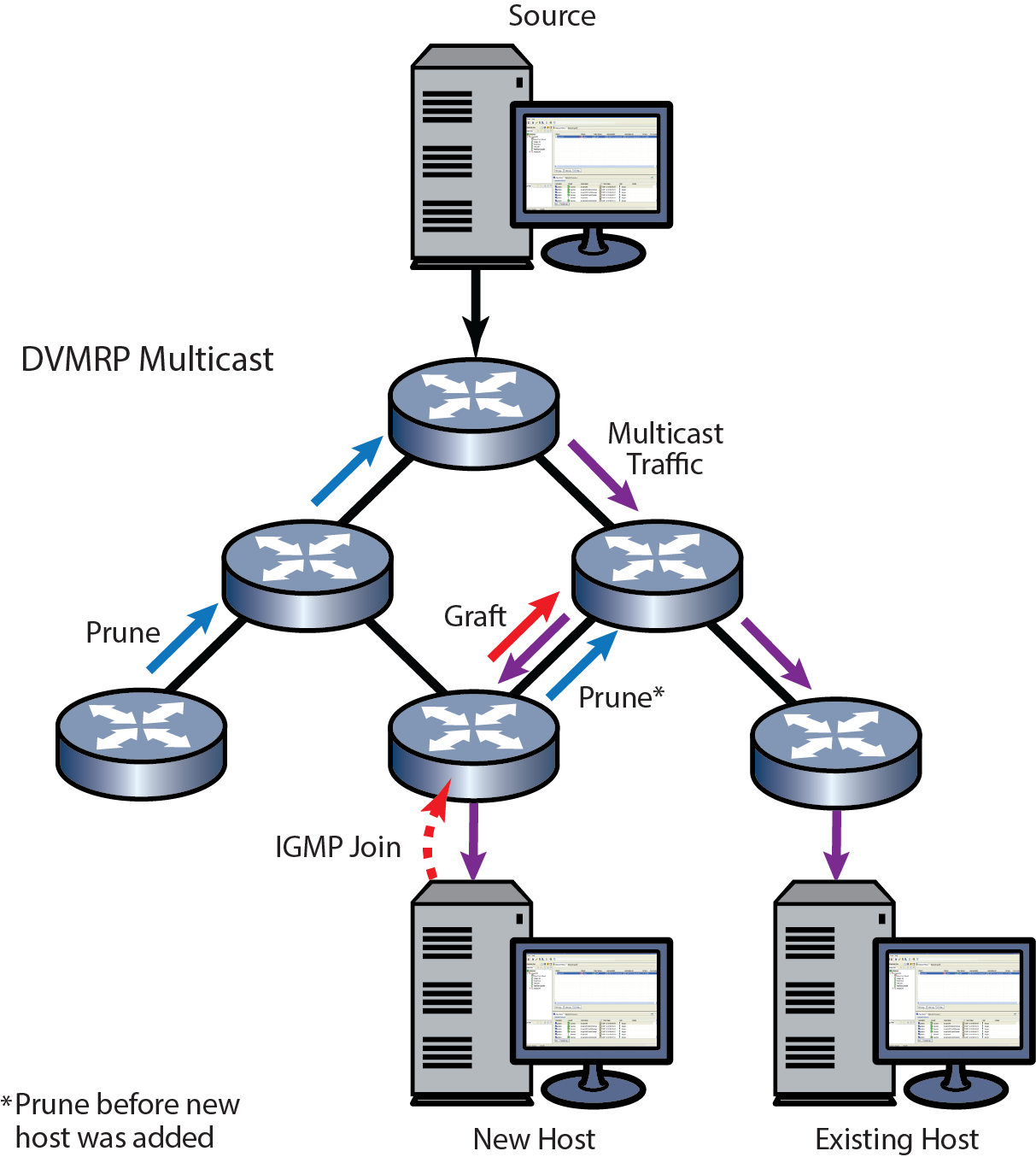
DVMRP Pruning and Grafting shows the DVMRP pruning and grafting process.
 Print
this page
Print
this page Email this topic
 Feedback
 View PDF
 Download EPUB