Using L3 tunnels, routers in the enterprise core are no longer part of the VRF configuration. The core routers transparently forward L3 VPN traffic to the tunnel endpoint using static routes or an IGP such as OSPF. The PE router uses a tunnel interface per BGP peer and encapsulates L3 VPN data as defined in RFC 4023, Encapsulating MPLS in IP or Generic Routing Encapsulation (GRE).
The Native MPLS encapsulation method implements the complete L3 VPN solution by replacing the need for tunnel interface in the L3 VPN configuration when MPLS is enabled on the routing interface. The MPLS label assigned by the MPLS router using the Label Distribution Protocol (LDP) contains the egress router path. All routers within the backbone must be MPLS capable routers when using Native MPLS. The Label Switch Router (LSR) uses the MPLS label to forward packets within the tunnel to the VPN egress router.
The required fully integrated services on the PE router for either a L3 tunnel or Native MPLS VPN network to establish are:
There are three router types in a typical L3 VPN network using L3 tunnels:
Imported L3 VPN routes learned on the PE router VRFs are redistributed to the customer edge routers using BGP.
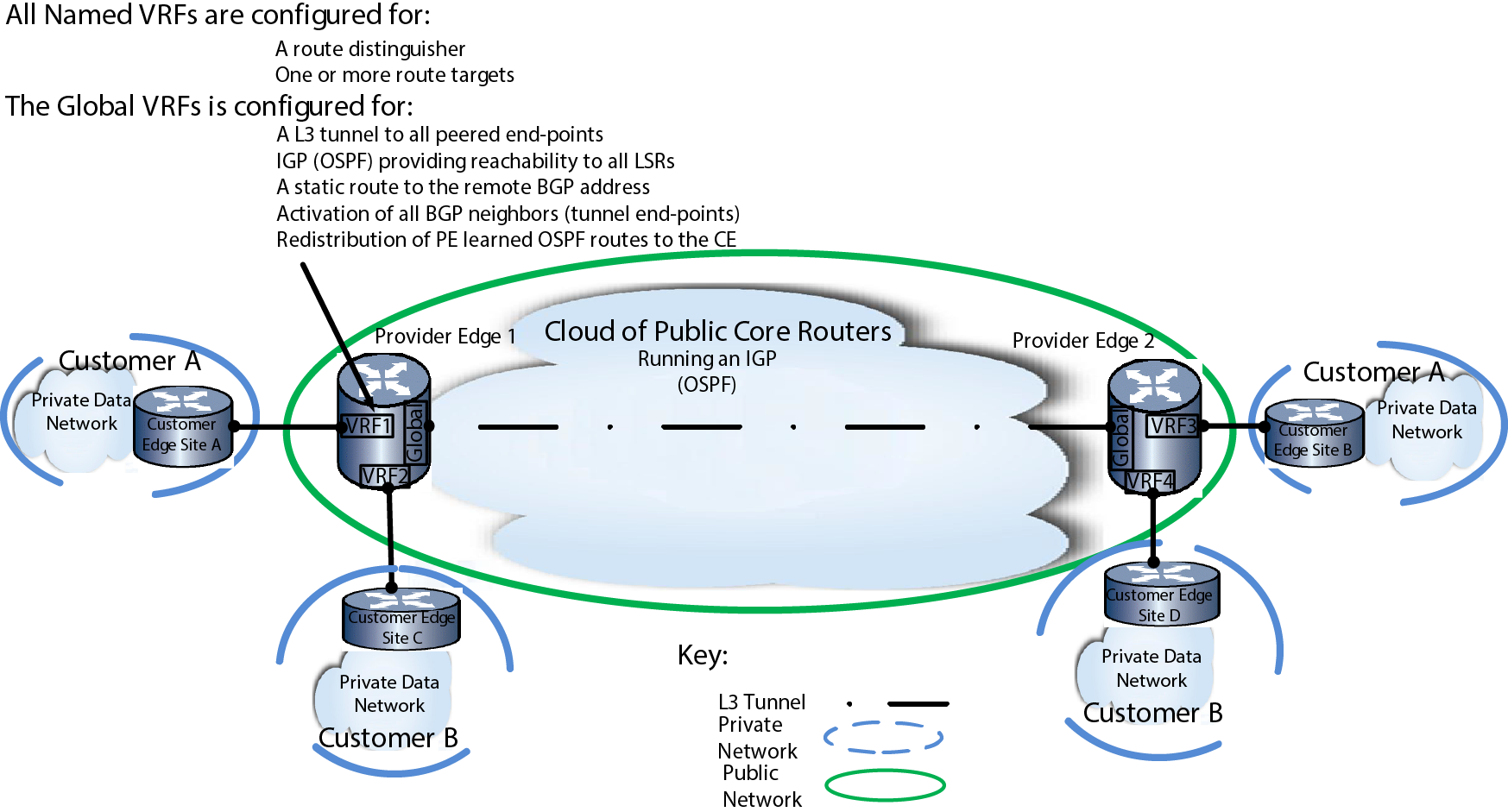
Layer 3 VPN Using L3 Tunneling Overview provides an overview of two L3 tunnel VPN networks, one for Customer A and one for Customer B, configured on two PE routers, with L3 tunneling providing the connectivity across the public core network.
Each PE router is configured for two VRFs, one for each L3 VPN. The L3 VPN for Customer A uses VRFs VRF1 and VRF3. The L3 VPN for Customer B uses VRF2 and VRF4. For a L3 VPN to operate, each VRF must be configured with an RD. Each VRF must be configured with at least one route target that imports or exports L3 VPN routes, or both imports and exports L3 VPN routes. Each PE peering must be configured with a L3 tunnel on the global VRF. An IGP protocol such as OSPF or static routes must be configured to provide reachability between all LSRs within the tunneled domain. Configure a static route with the remote BGP address as the destination, so that the remote peer‘s loopback address prefers the tunneled interface as the next-hop over the VLAN interface the tunnels use for BGP information. BGP must be configured at the global VRF to redistribute routes from each VRF to the linked CE router and to forward L3 VPN traffic over the L3 tunnels. The appropriate IPv4 or IPv6 BGP L3 VPN address family must be enabled. Within the appropriate BGP L3 VPN address family, activate each BGP neighbor.
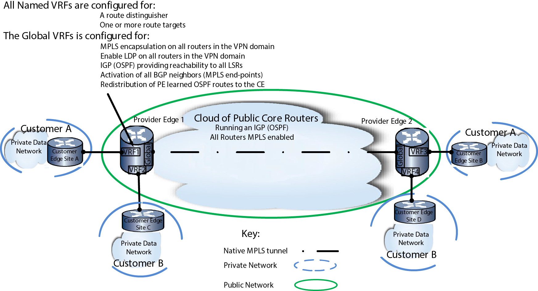
Layer 3 VPN Using Native MPLS Overview provides an overview of a L3 Native MPLS VPN network, with one Native MPLS tunnel for Customer A and one for Customer B, configured on two PE routers, with L3 Native MPLS tunneling providing the connectivity across the public core network.
Each PE router is configured for two VRFs, one for each L3 VPN. The L3 VPN for Customer A uses VRFs VRF1 and VRF3. The L3 VPN for Customer B uses VRF2 and VRF4. For a L3 VPN to operate, each VRF must be configured with an RD. Each VRF must be configured with at least one route target that imports or exports L3 VPN routes, or both imports and exports L3 VPN routes. Each PE and Core router in the L3 MPLS domain must be enabled for MPLS encapsulation at the global VRF. An IGP protocol such as OSPF or static routes must be configured to provide reachability between all LSRs within the tunneled domain. On each PE router, BGP must be configured at the global VRF to redistribute routes from each VRF to the linked CE router and to forward L3 VPN traffic over the L3 MPLS tunnels. The appropriate IPv4 or IPv6 BGP L3 VPN address family must be enabled. Within the appropriate BGP L3 VPN address family, activate each BGP neighbor.
 Print
this page
Print
this page Email this topic
 Feedback
 View PDF
 Download EPUB