A tunnel bridge port (Virtual Private Ethernet Service) is a virtual bridge port attached to a layer 2 tunnel router interface. Unlike a Virtual Private Port, which is a logical connection of the ingress port of one device to the egress port on another device located elsewhere in the network, a tunnel bridge port permits the transparent connection of two disjoint bridge infrastructures over an intermediate routed network, while preserving the simplicity of a bridged network and providing all of the failover features provided in the bridge protocols between the two disjoint bridged networks.
The tunnel bridgeport binds a tunnel bridgeport and a relookup port. This binding is required because the tunnel bridge port does not have a native hardware port. The relookup port is a front panel physical port (not supported for 8.21) that has no customer facing controls or an internal virtual port assigned by the system that is used as a tunnel bridge port‘s underlying port. The relookup port loops a packet back to the switch for further transformations, such as to program multicast group IDs or connections. If the relookup port is a physical front panel port, the port is placed into loopback mode and becomes dormant, providing functionality similar to an internal relookup port.
The tunnel bridgeport is bound to the routing tunnel interface using the tunnel mode gre L2 command.
The tunnel bridge port is specified as tun.0.y where y is the tunnel bridge port number.
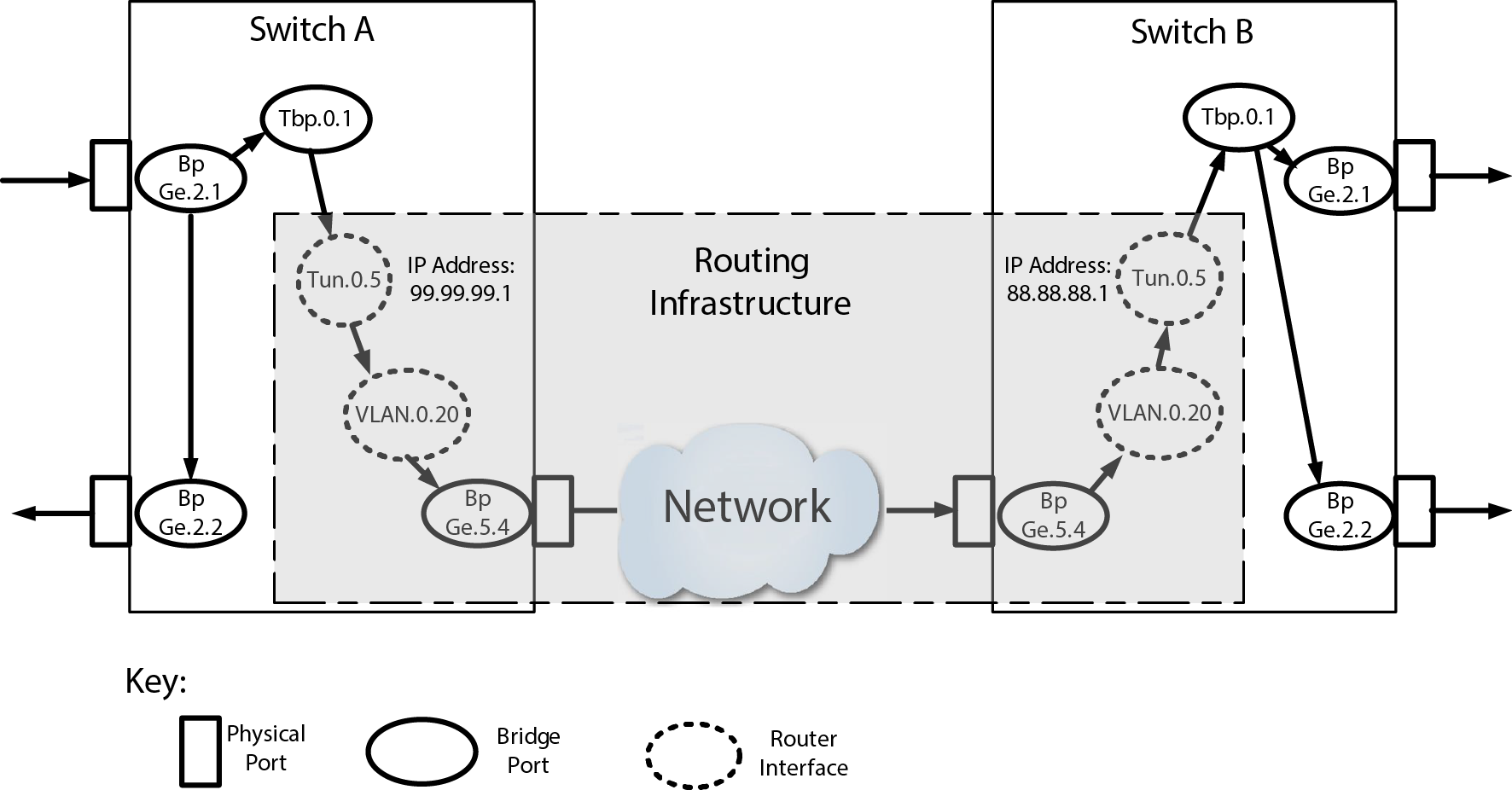
L2 Tunnel Bridge Port Configuration Example displays a L2 tunnel bridge port configuration example. In this example, the switch configurations include:
A packet arrives at bridge port ge.2.1 and is flooded to the egress list of VLAN 10. The tunnel bridge port tbp.0.1 is on this egress list, so a copy of the original packet is encapsulated and routed to switch B, where it is decapsulated and flooded to VLAN 10 on that switch. Since the SMAC of the first packet has now been learned on bridge port ge.2.1 on switch A and tbp.0.1 on switch B, packets returning along this path do not flood.
This example shows how to configure Switch A for tunnel bridge port tbp.0.1 bound to GRE L2 tunnel 5:
System(rw)->configure
System(rw-config)->interface tunnel 5
System(rw-config-intf-tun.0.5)->tunnel source 99.99.99.1
System(rw-config-intf-tun.0.5)->tunnel destination 88.88.88.1
System(rw-config-intf-tun.0.5)->tunnel mode gre l2 tbp.0.1
System(rw-config-intf-tun.0.5)->no shutdown
System(rw-config-intf-tun.0.5)->
Configuration on Switch B is the same except for reversing the tunnel source and destination addresses.
 Print
this page
Print
this page Email this topic
 Feedback
 View PDF
 Download EPUB